This part is not very complicated, it is quite long because it’s necessary to cut all the cables to the right length and to weld or to crimp the differents plugs, all the most clean and without wiring error, so take your time !
Before cutting any cable, place the printhead away from the Ramps 1.4 box, at the top and towards the power supply.
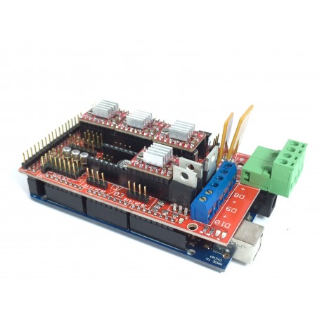
Put the 3 jumpers under each pololu (drivers) and place the drivers on the ramps as the picture below.
Observe in which direction are the small potentiometers of the drivers A4988 (green or red)
For drivers DRV8825 (purples) potentiometer is in other side!)
Now switch on wiring, check and double check, and once you are sure of you, check again the good connection and especially the polarity of each branch! You can click on the pic to enlarge.
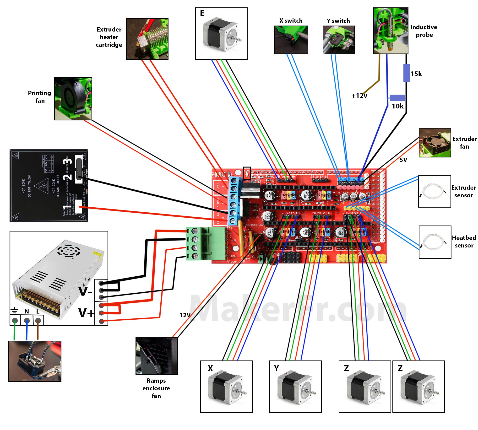
Warning ! Some power supplies do not support the shunts as shown in the diagram, try first without the shunts, the shunts only serve if the tray fails to reach 100 ° for printing the ABS
The lighting leds is not on the schematic, you can plug it into a 12v input from the Ramps 1.4
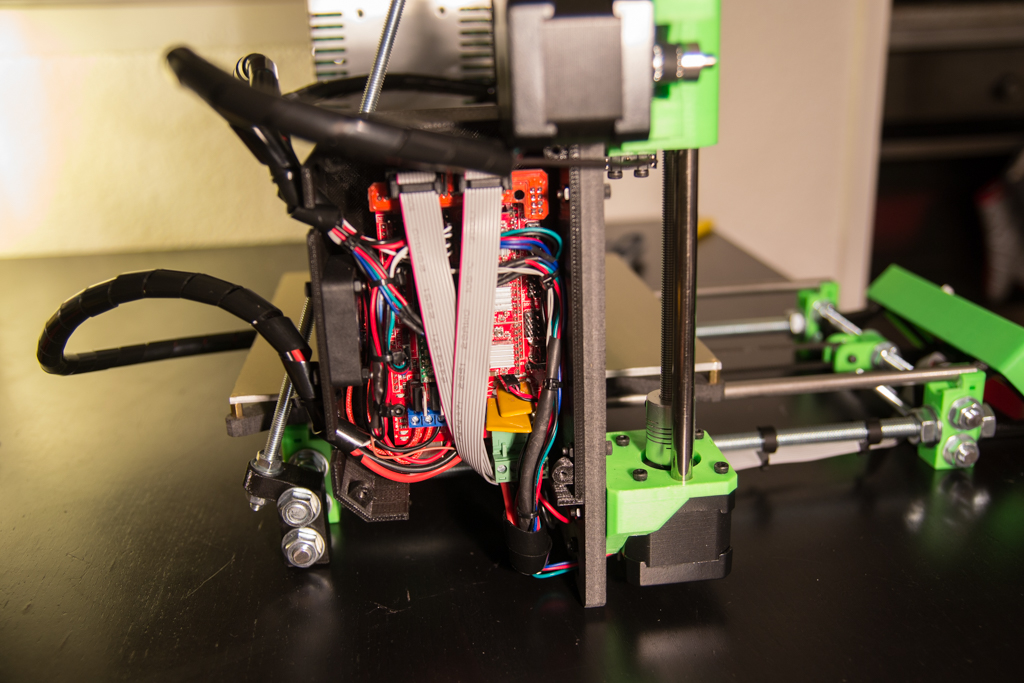
Sheath all wires :

Before connecting the wire layers of the LCD, make sure that no wires touch the Mosfets surrounded in yellow, because they will heat up very strongly and will melt the insulation of any wire that will contact and create a short circuit!
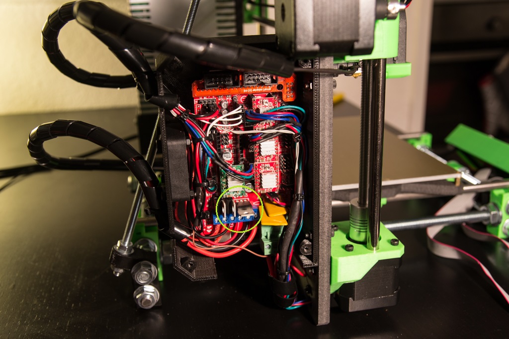
We check that the LCD wires don’t touch the Mosfets… And don’t invert “EXP1” and “EXP2” plugs !
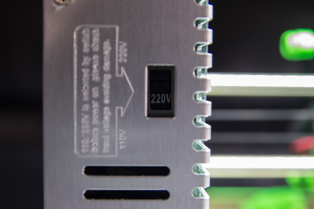
And don’t forget to check that the power supply is set to the correct voltage for his country!
Now you can turn on the power to check that you have correctly connected all the wires … If there is a short circuit, you’ll quickly know ^^.
What should be noted at this stage: The enclosure fan and extruder fan must run (not the printing fan, normal). The induction probe red LED lights up when you put metal underneath. The LED strip is lit, the LCD backlight is lit but no writing is present, this is normal, we will now move to the software section !
Good day! I know this is kind of off topic but I was wondering if you knew where I could find a captcha plugin for my comment form? I’m using the same blog platform as yours and I’m having problems finding one? Thanks a lot! gdeeggeadfee
Hi, I don’t use the captcha platform, comments are original on wordpress !
Thanks for great build . Would you be able to make video tutorial as well for assembly and wiring. That would be great for starters. Thanks
Hi ! Thank you
I will surely make videos but not now because I have a lot to do before 😉
Which wire sizes do you use for the power supply to the ramps board?
Hi! I did not measure but about 50cm from the power supply to the ramps and 40cm from the Ramps to the heatbed
not length, what gauge?
You wants know the diameter ? In the non-printables parts i said “Cable pair, 16AWG (1.25mm²) 1 meter “
Did you remove the led on the ramps?
No ! why ?
I accidentally got a 240W power supply that only has four screw terminals for the positive and negative 16 gauge wires. I was trying to heat up my bed and my power input connector melted. is this because of a lose connection or not enough wattage?
The first thing to check is the impedance of the heatbed terminals which must be around 1.2 ohms.
Measure it and tell me.
My multimeter is reading around 2 ohms.
Is it the connector of the ramps that has melted? If yes it happened to me, it was because of a false contact that created an electric arc, I solved the problem by welding a new connector.
For this kind of technical question it is better to use the forum.
Have a good day
Bonjour,
je suis très intéressé par l’assemblage de cette imprimante 3D (en espérant que les pièces imprimées seront prochainement disponibles) mais j’ai des questions :
1 – serait-il possible de détailler un peu l’assemblage du kit Ramps 1.4 en lui même (il n’y a rien sur Banggood)
Par exemple “Mettez les 3 jumpers sous chaque pololu” n’est pas évident à comprendre, même si j’ai vu sur internet qu’il s’agit des drivers des moteurs.
Il y a 5 drivers livrés dans le kit mais 4 “axes” sur la machine (X,Y,Z + extrusion). On peut deviner où les mettre, mais c’est “deviner” qui me gêne un peu.
2 – Si les Mosfets chauffent, est-il possible d’ajouter des dissipateurs, quitte à la limite à les dessouder pour les déporter.
Merci
Bonjour,
Remarque pertinente ! des drivers A4988 se montent comme ceci sur la ramps http://www.funreprap.com/43-large_default/shield-ramp-s-14-seul.jpg (bien observer de quel coté est le petit potentiomètre de chaque driver) (Le potentiomètre se monte de l’autre coté avec des drivers DRV8825)
Je vais éditer l’article afin que les débutants ne se posent plus ce genre de question.
Pour les Mosfets, je déconseille de les déporter, au pire oui, on peut y ajouter un dissipateur, mais la place manque.
Romain
Bonjour,
Qu’est ce qu’il y a sous la gaine thermo se trouvant sur les fils des moteurs ?
Le 12v du capteur inductif tu le récupéres où ?
Existe il une sortie en 5v pour alimenter des leds?
Merci
Bonjour,
La gaine thermo de fils des moteurs est là juste pour faire joli.
Le 12v du capteur inductif se récupère sur l’entrée 12v de la ramps
La réglette de leds s’alimente en 12v
Romain
Bonjour et merci pour la réponse. Je demandais cela car j’ai une réglette 5v que j’aurais aimé récupérer.
Je n’ai pas trouvé de drawing pour la 1.4 sur le net.
Une fois de plus super boulot et merci d’être réactif dans tes réponses
De rien Guillaume, par contre si t’as d’autres questions, ce serait bien de les poster sur le forum 😉
Bonjour,
Tout d’abord merci pour ce super site je suis en plein montage de ma I3-R.
Pour les sections de fils tu as utilisé du 1,5mm2 et du 0,75mm2 ?
– 1,5mm2 pour une partie de l’alimentation et pour le plateau.
– 0,75mm2 pour tout le reste.
C’est bien ça ?
Oui c’est bien ça !
Romain
bonjour je tenais a vous faire partager mon probleme! drivers en court-circuit faite gaffe au soudure sur la puce sur le drivers, ca fait peter le regulateur!!!
Ha oui où avais tu un court circuit ? sur le driver ou sur la Ramps ? Le driver était bien mis à l’endroit ?
Donc un court circuit sur le driver [soudure sur deux pattes] qui a provoqué la destruction du régulateur de l arduino. En rebranchant tout sur le pc et retirant les drivers j’ai vu que ça démarré donc je l’ai est remis un par un et donc le driver défectueux.
J’ai recommandé un régulateur on verra bien
Hello,
I tried to register in the forum, but all i got ist that the registration needs to be approved by the admin. Therefore i put my question here.
The jumper setting for the steppers is still an open question.
According to your assembly we should put all 3 jumpers, this sounds strange.
I have done some research and found that the jumpers are here for adjusting the number of micro steps. It further depens which drivers we use. What i found is, that putting all 3 jumpers would mean the drivers schoul work in 1/128 step mode.
Afaik the drivers we use are not able to do that. Can you pls. expalain it.
The following is from this source:
https://chinadrucker.de/2017/3d-drucker-aufbau-umbau-auf-ramps-1-4-am-beispiel-anet-a8-inkl-marlin-installation/
jumper Yes/No step size
1 2 3
no no no full step
yes no no half step
no yes no 1/4 step
yes yes no 1/8 step
no no yes 1/16 step
yes no yes 1/32 step
no yes yes 1/64 step
yes yes yes 1/128 step
Hello,
No, it will not work in 1/128 th of a step, it depends on the driver used, your source is strange ! See that : http://www.reprap.org/mediawiki/images/0/06/RAMPS_dossier.pdf
With a A4988 driver and 3 jumpers it works in 1/16th of step
With a DRV8825 driver and 3 jumpers it works in 1/32th step
In the section software there is one firmware for each driver used, one for A4988 drivers and one for DRV8825 drivers, this takes into account the microsteps of drivers used.
Sorry if I have not activated your account but as I have too many spam, I am obliged to remove suspicious entries, I must notify me by email if it takes too long to activate 😉
Thanks for clarifiaction. Now I continue wiring. The Frame is setup. Only the Extruder Stuff has not arrvied from china yet.
Cheers
Ernst
Really thanks man!