Before starting the assembly, I just want to give two or three tips for cutting and drilling parts.
Drilling:
- Place the plastic part or printable template on the part to be drilled.
- Using a pencil or a tip, draw the holes to be drilled on both sides of the mason box screed so that the holes are facing each other.
- Remove the template or plastic part
- Point with a needle
- Drill with small front hole (3mm) before drilling to 6mm or more.
Aluminium box screed cutting (It goes of the final geometry of your CNC!):
- Observe precisely the measures
- Draw the cutting line with a square, and on both sides!
- Recheck the measurement after cutting, deburring and filing if necessary.
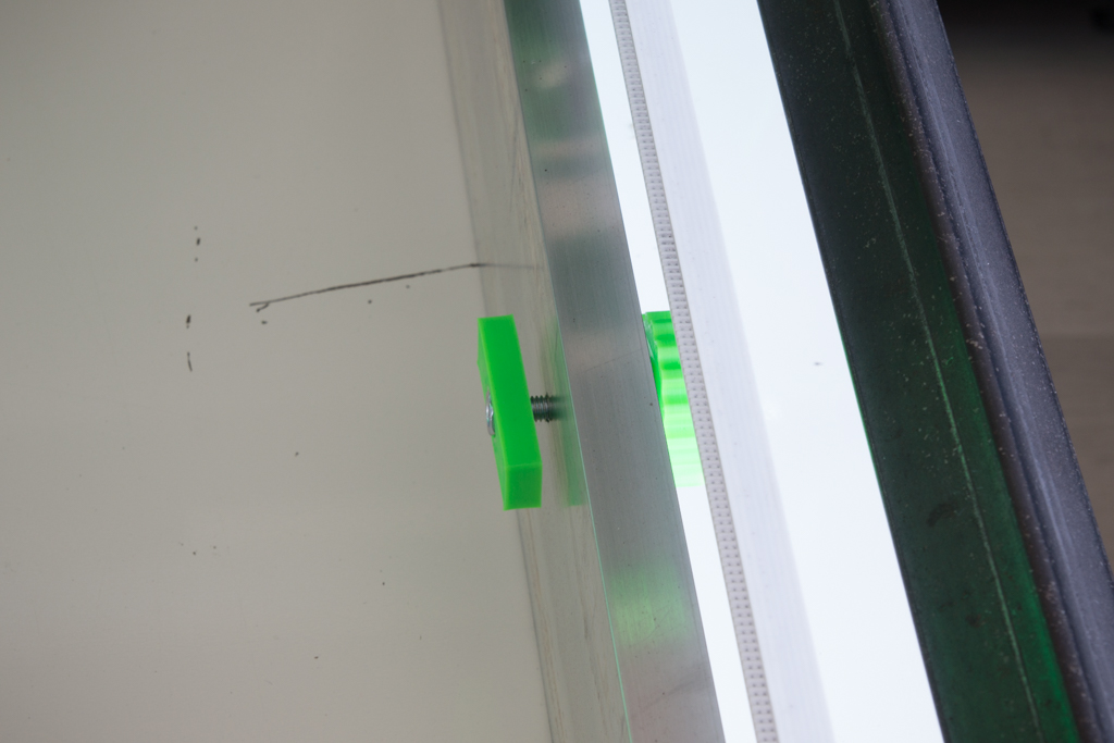
To tighten the screws through the box screed, go quiet, don’t crush the aluminum, a light tightening is enough, put brake nuts or a drop of brake net. If you really want to squeeze like crazy, you can clap 15mm MDF in box screed ! Personally I have not put and it does not move once the editing is finished, it is not a question of strength but geometry;)
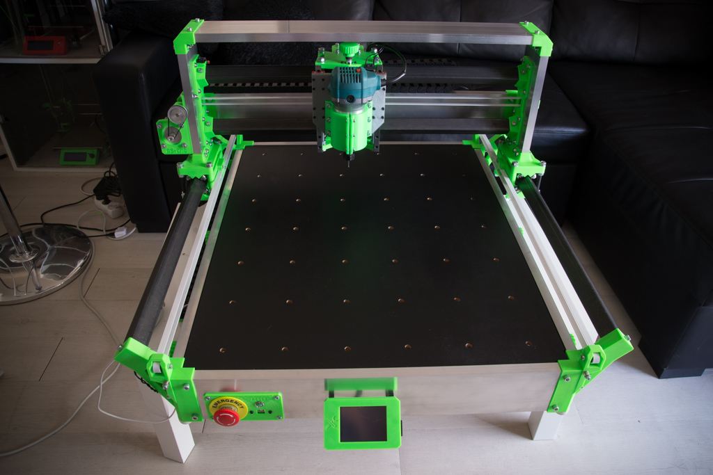
We can start 🙂
NEW You can download the PDF assembly manual made by HTheatre from the forum 🙂
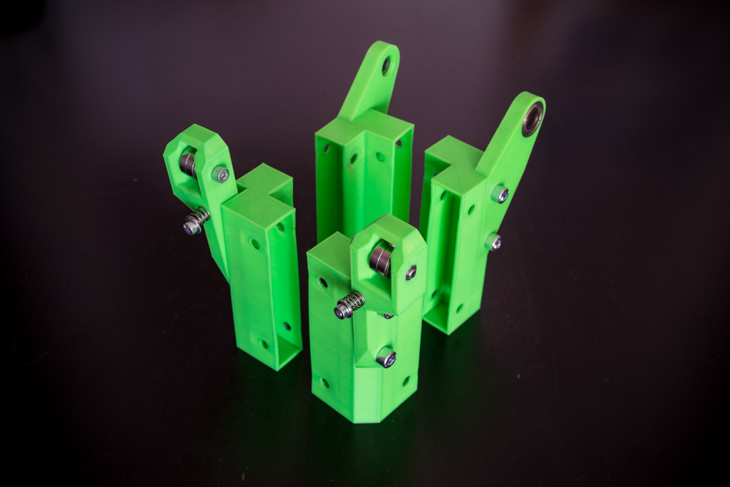
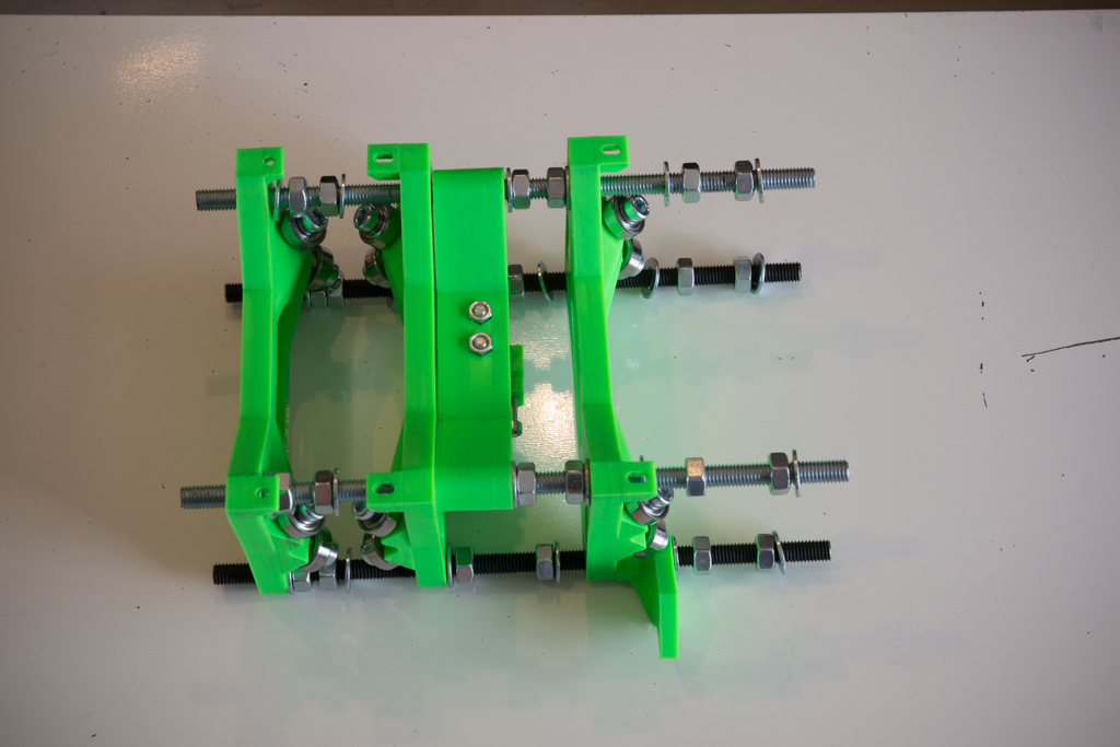
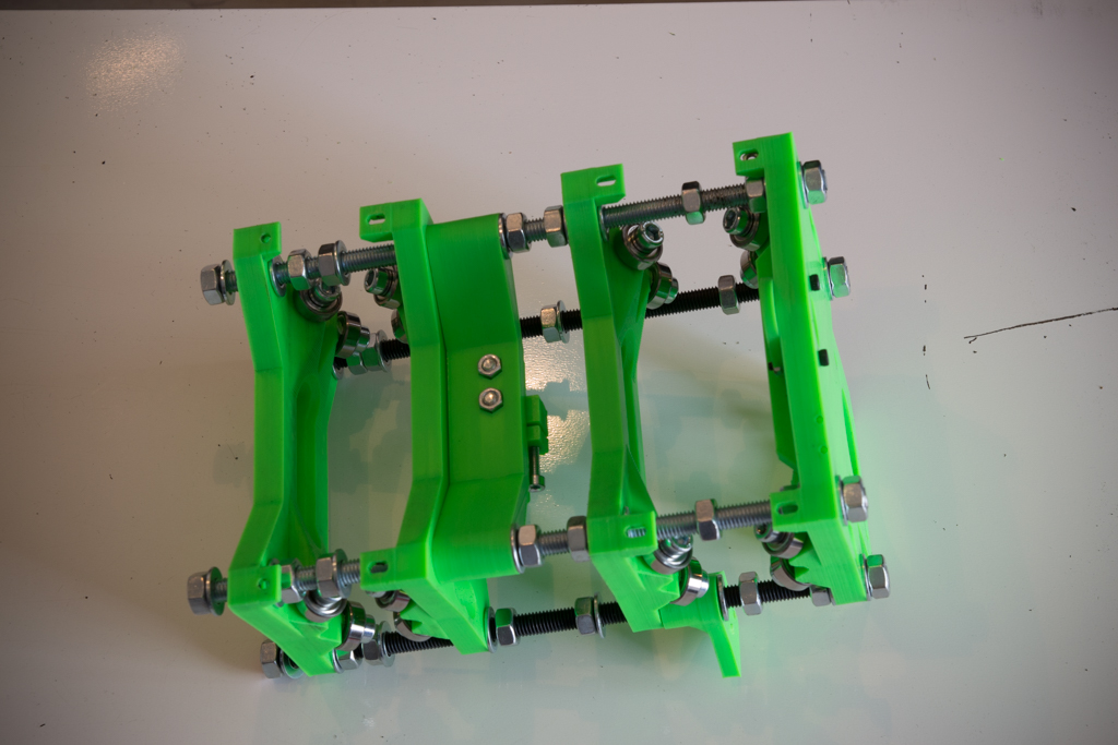
- Take the 4 printable corners and mount them like this with the 2 bearings 608zz for the rear parts, the two pairs of 625zz for the belt tensioners, the two screws m4x40 and the two springs (optional)
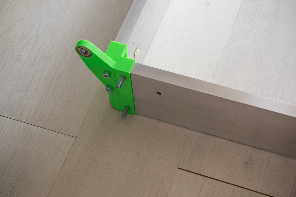
- Take the box screed of 600 and 750mm and nest them like this below then draw the holes on both sides, dislocate the pieces, point and drill at 6mm.

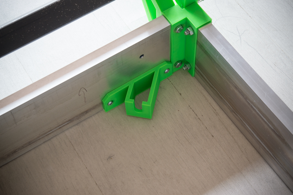
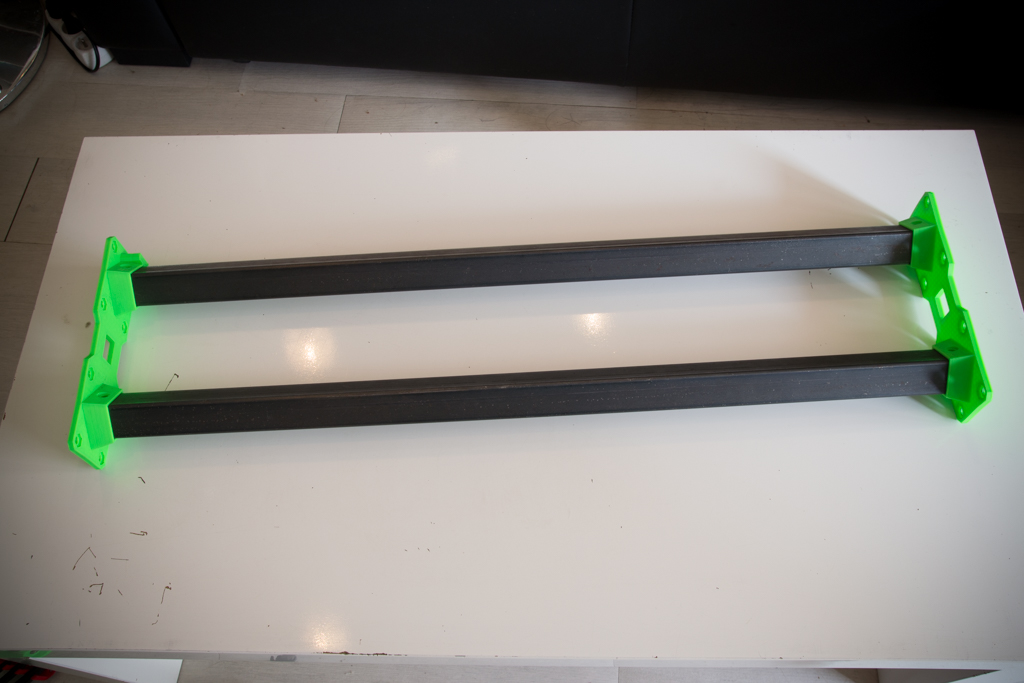
- Take the square tubes of 746mm, nest their supports, trace the holes, point, drill at 6mm, and screw them.

- Insert the 8 screws that hold the Y rail brackets
- Then screw the rail supports at first, then put and tighten the other screws of the 600mm mason rules.
- Position the fasteners of the threaded rod M10 in contact with the printed corners and at the bottom of the box screed, drill and screw with sheet metal screws
- Position the threaded rod m10 in its supports
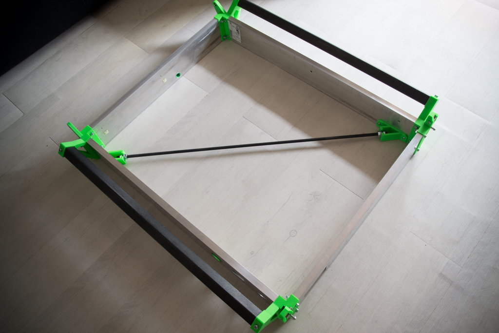
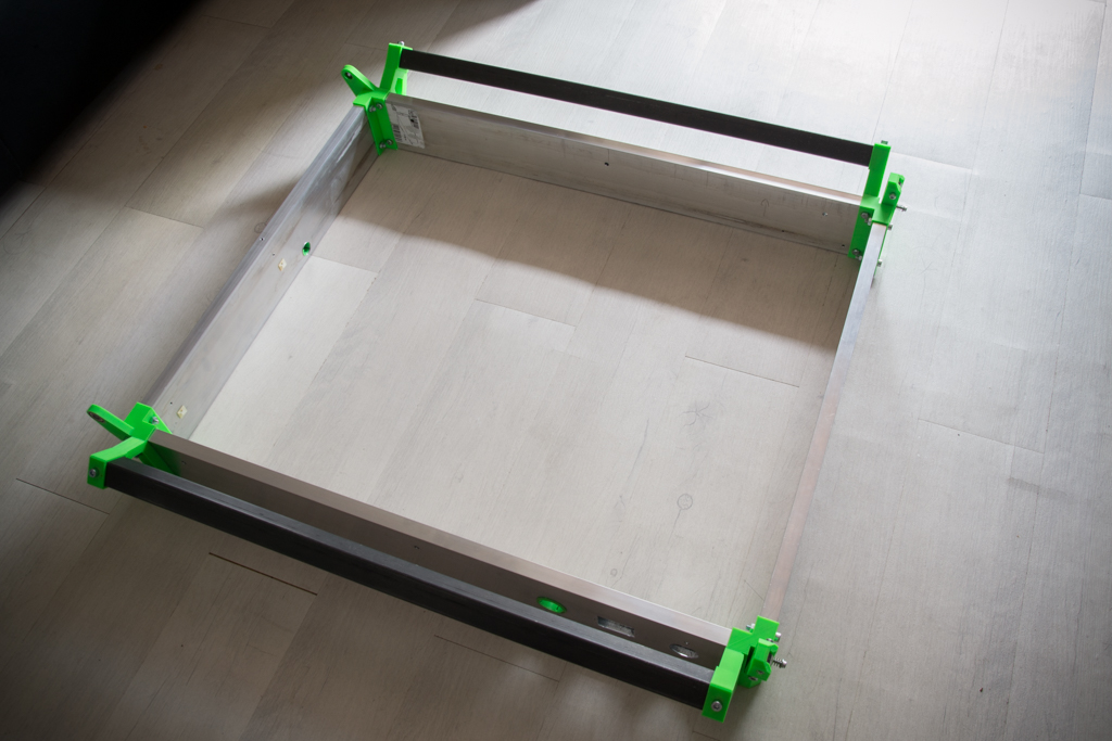
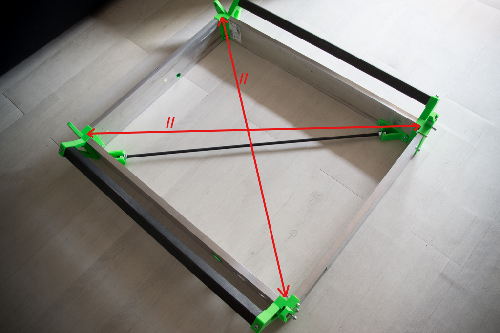
- Carefully adjust the perpendicularity of the assembly by having the same measurement on both diagonals then tighten the nuts of the threaded rod, then check that it has not moved while tightening.
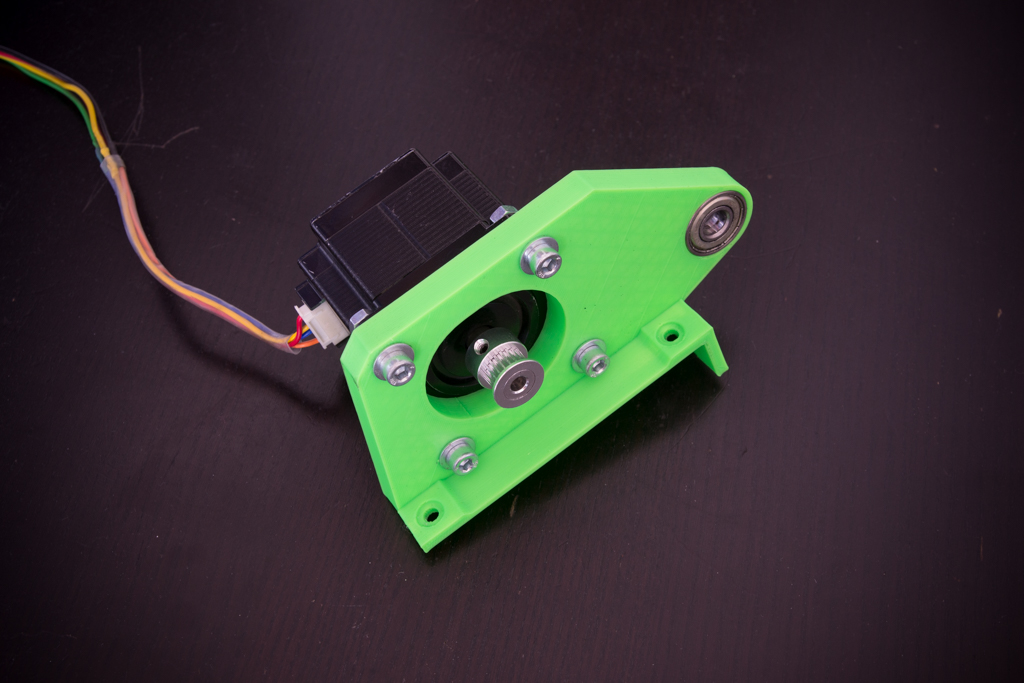
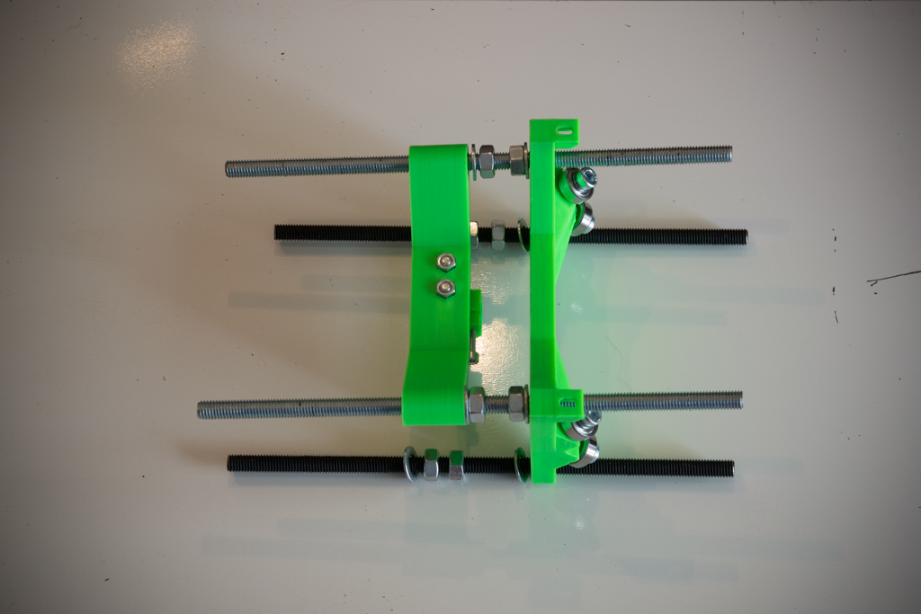
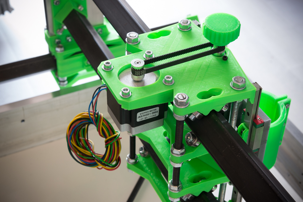
- Take the printed part of Y motor support , insert the bearing 608zz and screw the nema 23 (without tightening for the moment)
- Put the piece in the middle (we are not to the millimeter for this measure) then point the holes, drill and screw with sheet metal screws. (think of making a hole through the box screed to get the motor wires to the back of the motor)
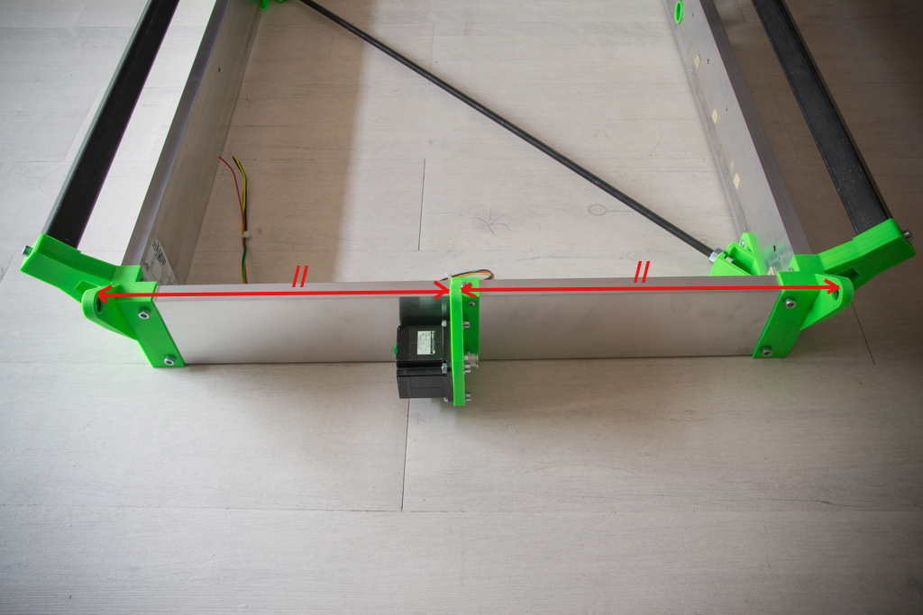
- Insert the smooth rod of 8x688mm by threading a washer, the pulley 60 teeth, the belt and then the pulleys 20 teeth at the ends as in the photo
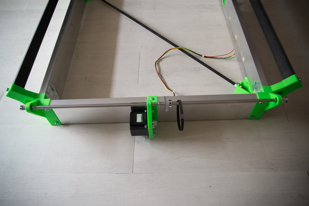
- Put everything in place and tighten
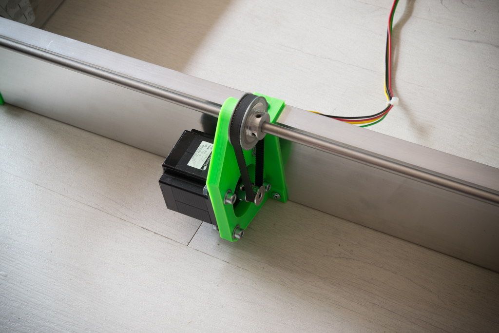
Plate making
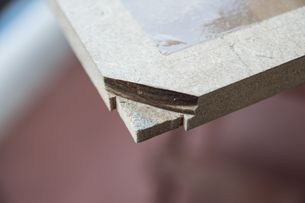
- Take your wooden tray and cut the 4 corners like this so that it fits

- Then remove the material below the corners to avoid being bothered by the screws below and that the tray can get to the box screed
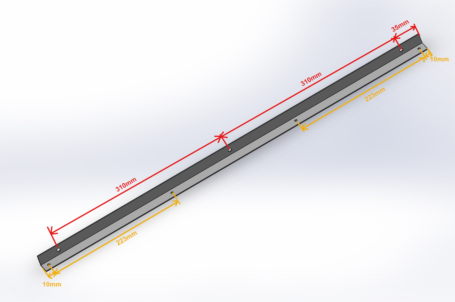
- Take the aluminum angles 20x20x690 and drill them like this:
- Holes measured in red are 10mm from the edge and drill at 6mm
- Holes measured in yellow are 10mm from the edge and pierce at 4.5mm
- Put on a flat surface 4 objects of the same thickness (here rolls of large tape) put the tray upside down, then put the frame of the RS-CNC upside down.
- Position the angles
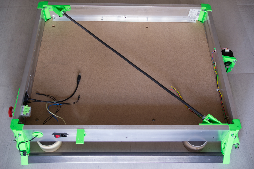
- Screw them first on the tray on the side of the 4 holes
- Then point the 3 holes on the box screed and drill to 6mm

- Open the 3 holes of each angle by cutting the red lines on the pic:

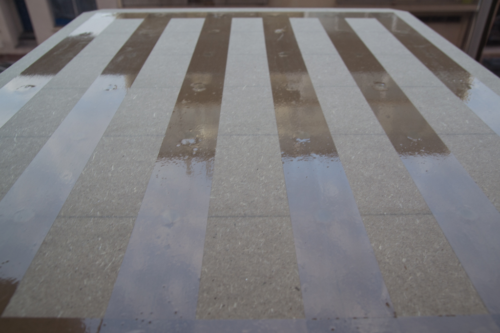
- Trace the clamps fixing holes on the plate
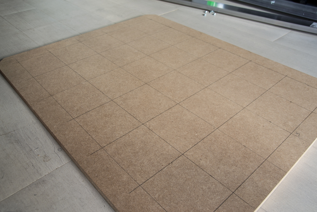
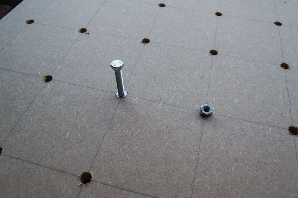
- Drill everything at 9mm
- Then from below, drill at 13mm only on 10mm depth
- Hammer an M8 nut into each hole (If you have neighbors, do it at a correct time so they do not hate you 😀 )
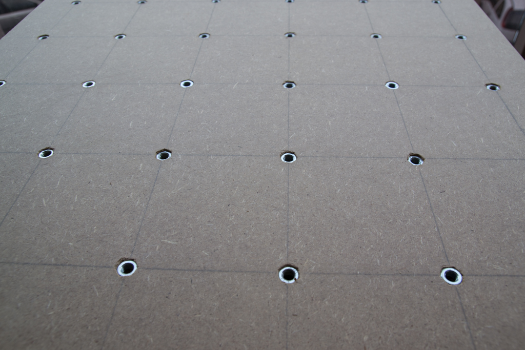
- Put large tape on top of each nut to prevent dust from passing through
- You can screw reinforcement angles under the tray if you wish
- Paint the top of the plate
- Put it aside for the moment
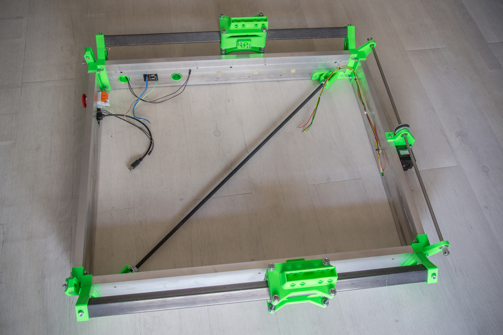
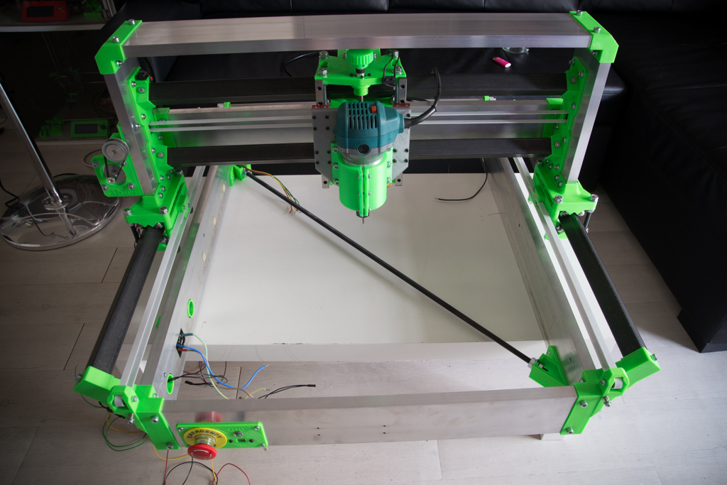
Back to our frame
- Screw the bearing 606zz on the 4 “Dollybase”
- And we start assembling like this
- We finished up on the rails in this direction (check the picture!)
- For tightening, it is necessary to tighten neither too much nor not enough, it is necessary that each bearing is in contact, without that it creates big hard points, it must circulate by hand resisting a little but not too much

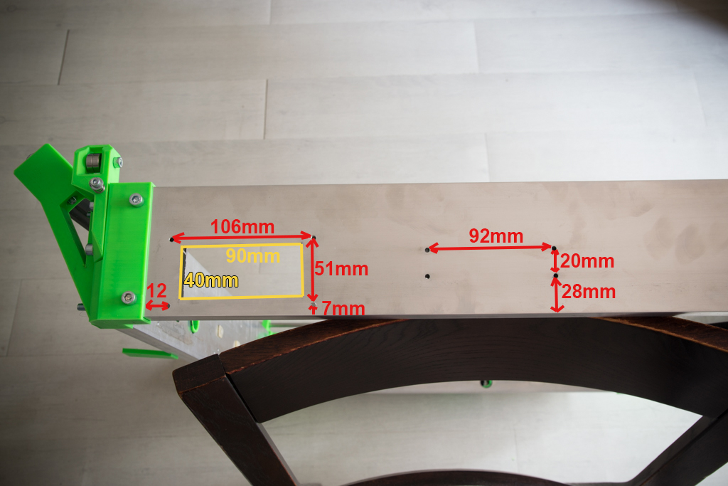
- Cut out and drill the box screed from the front face like this (the 4 holes and the left cutout are made for the front panel plate, the 4 right holes for the TFT screen bracket, the holes for the plate buttons are not through because it is screwed with sheet metal screws, the TFT fixing holes are 3mm and through)
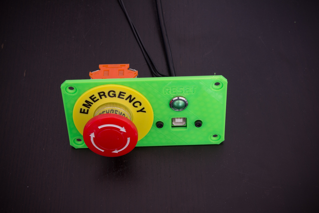
- Once done, you can assemble the button plate like this and screw it on the frame
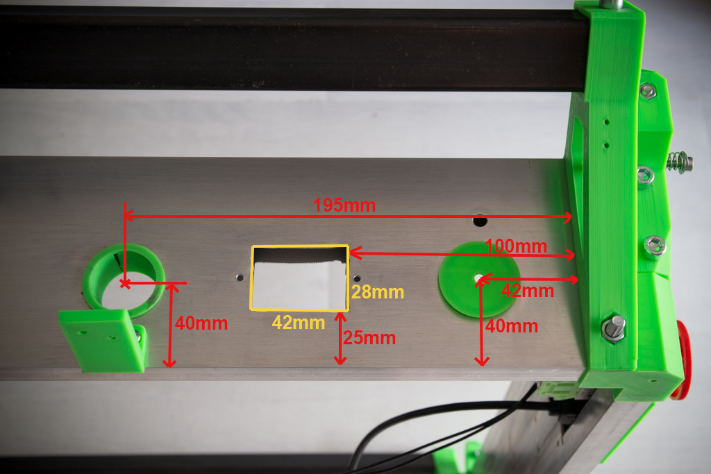
- Now drill and cut like this the box screed on the left side of the machine (the 31mm hole on the right was plugged with a printed part because I recycled the box screed of my old R-CNC)
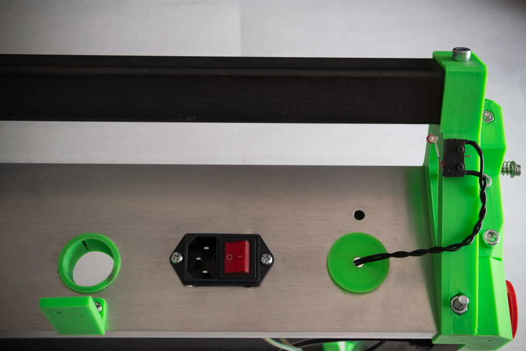
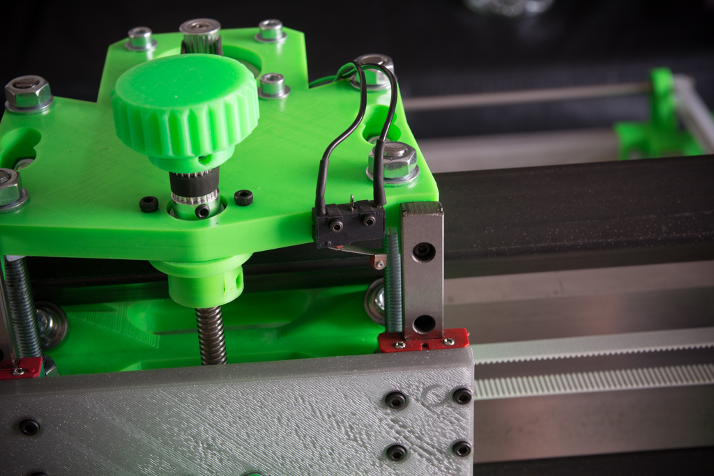
- Then screw on the plug / switch module and switch Y (to be wired in “normally closed” “NC”)
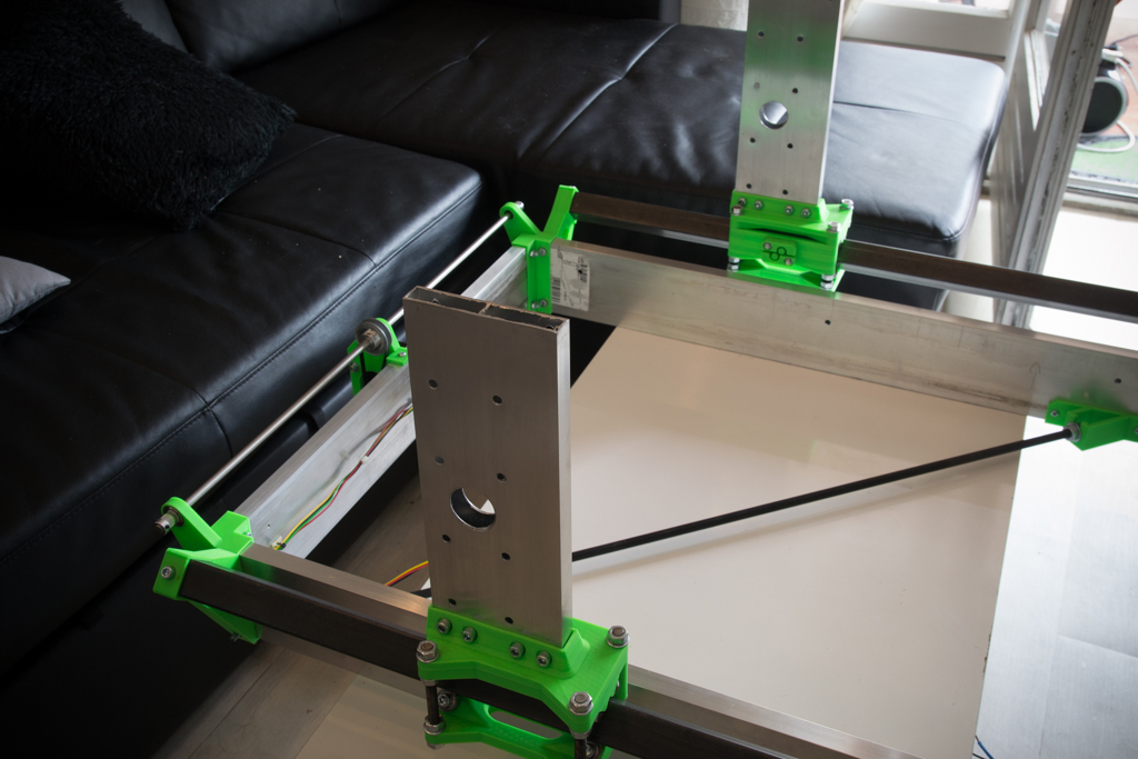
- Take the two box screed of 266mm and put them in place
- Set up the drilling model and report all the holes
- Do the same on both sides of the two box screed
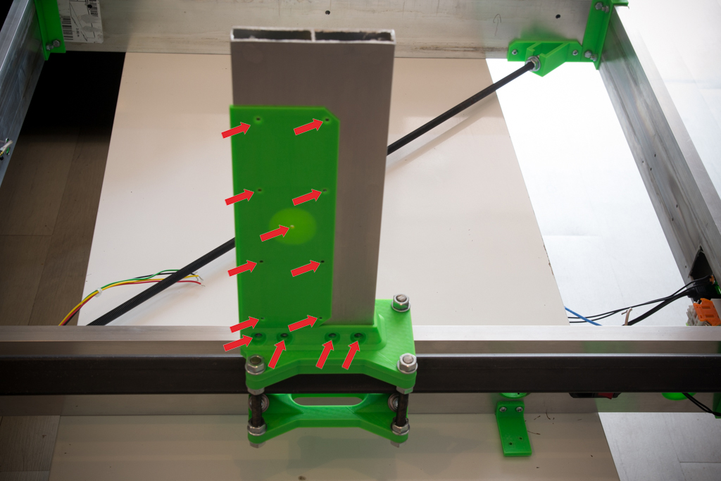
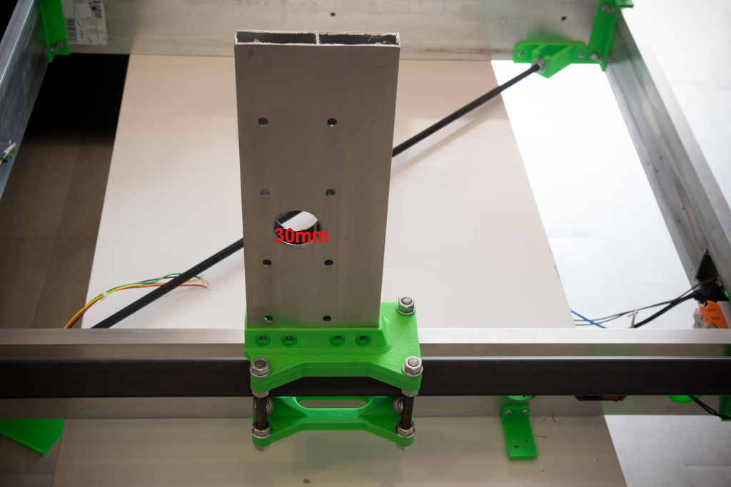
- Drill all the holes at 6mm except the big central hole at 30mm
- Screw the box screed to their base
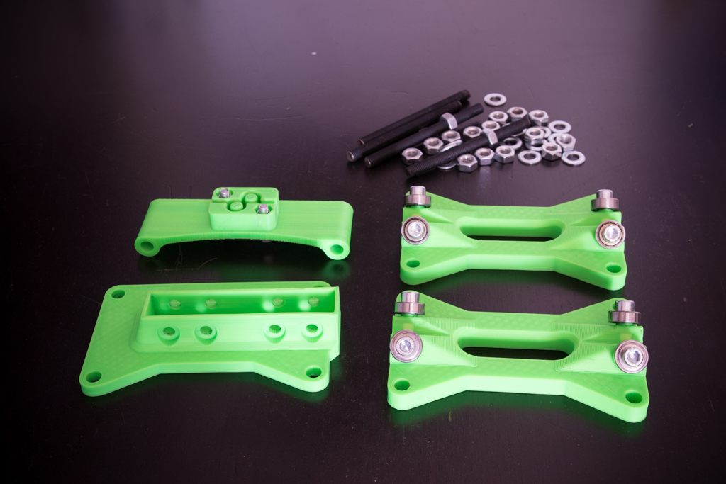
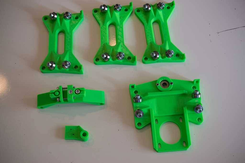
- Prepare the parts for the X / Z module
- Screw all 606zz bearings with M6x20 screws
- Insert the 608zz bearing on the dolly_top and screw in the locking piece.
- Screw the X strap fasteners
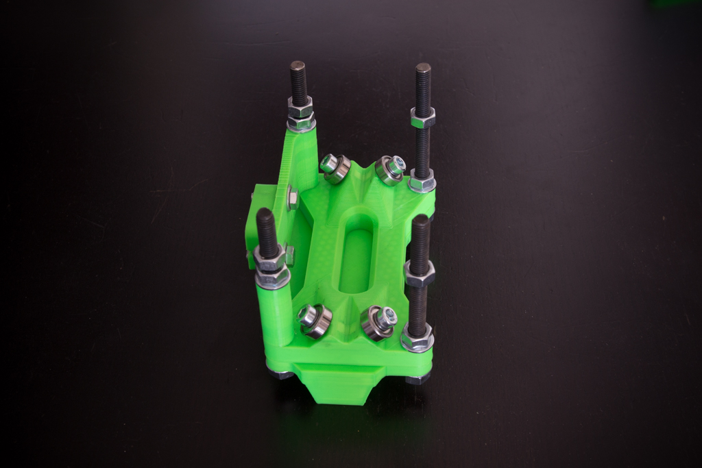
- Assemble the module like this:


- Take the square tubes, put them in their supports, postpone the holes and drill to 6.5mm
- Thread the X / Z module (nuts not tightened)
- Put the screws through the square tubes and tighten
- Do not tighten the X / Z module yet

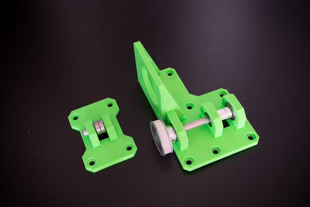
- Prepare the X belt parts as follows:
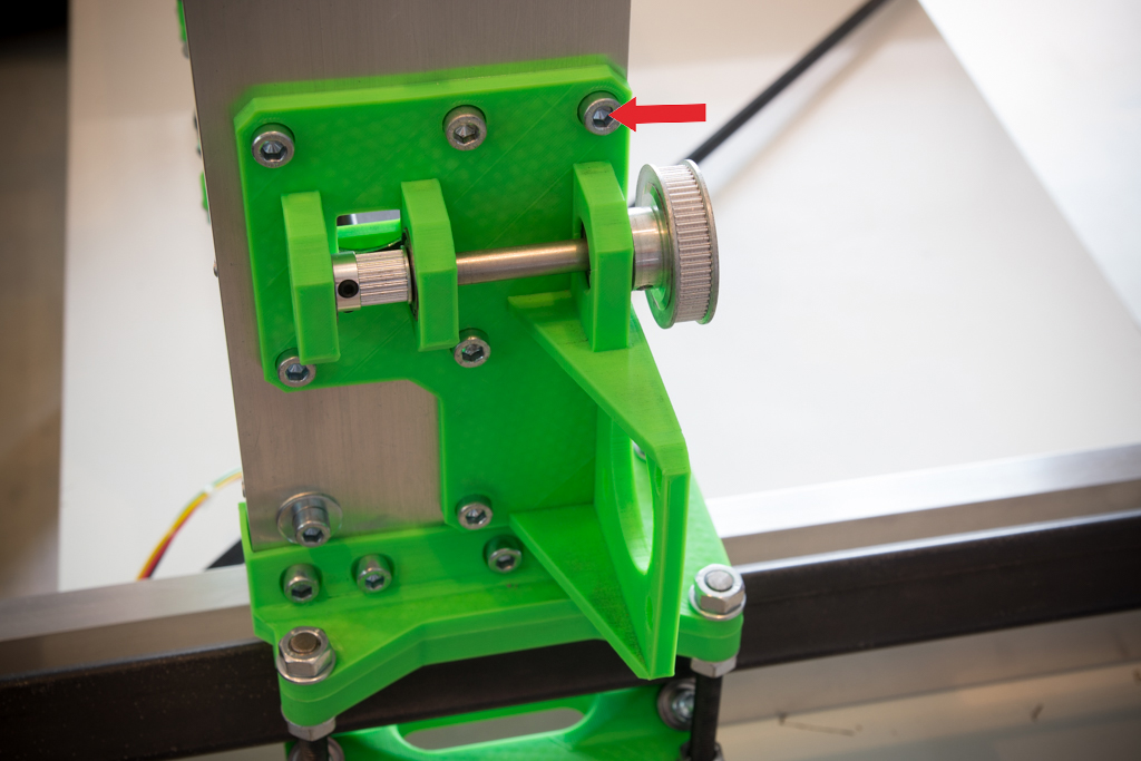
- Put the left piece in place
- Report the marked hole with the red arrow
- Drill the hole
- Fix the piece to the box screed
- Seen on the other side:

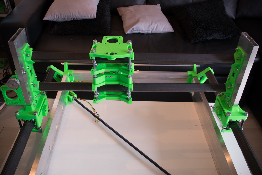
- Overview at this point
- Adjust and tighten the nuts of the X / Z module
- All bearings must be in contact with the square tube (put your finger on each bearing and move the carriage to see if the bearing is driven)
- Do not compress the square tube too hard otherwise it will cause hardness in the mechanical movement
- The pressure should not be too low either at the risk of having play
- The good pressure of the bearings is when you can move the module with a little resistance but not too much

- Fix the MGN12 rails of 200mm each
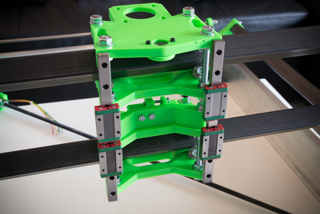
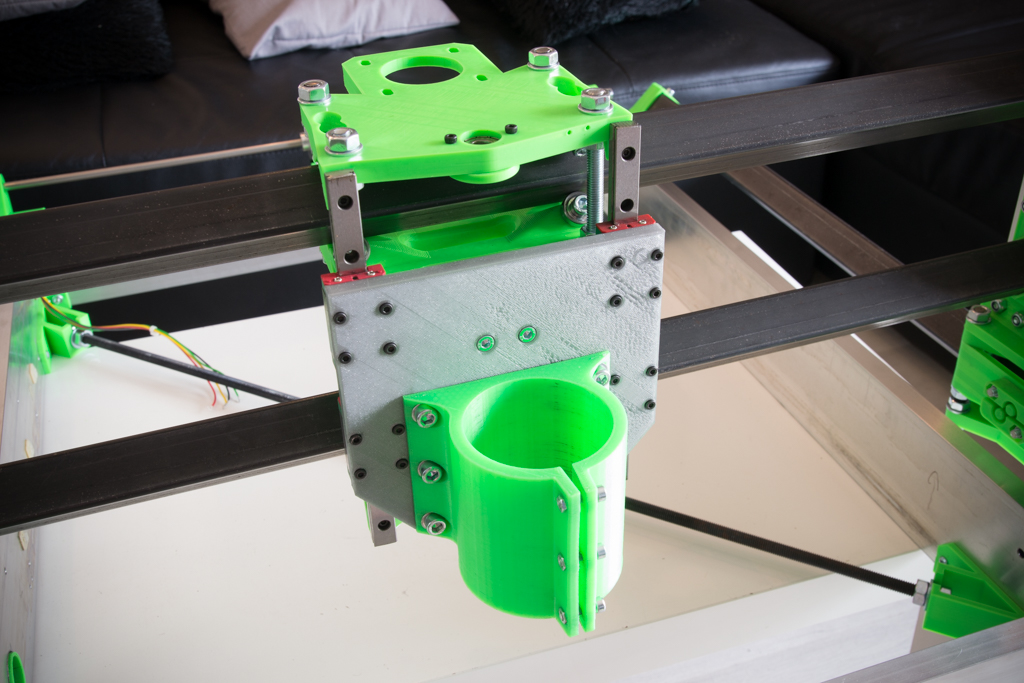
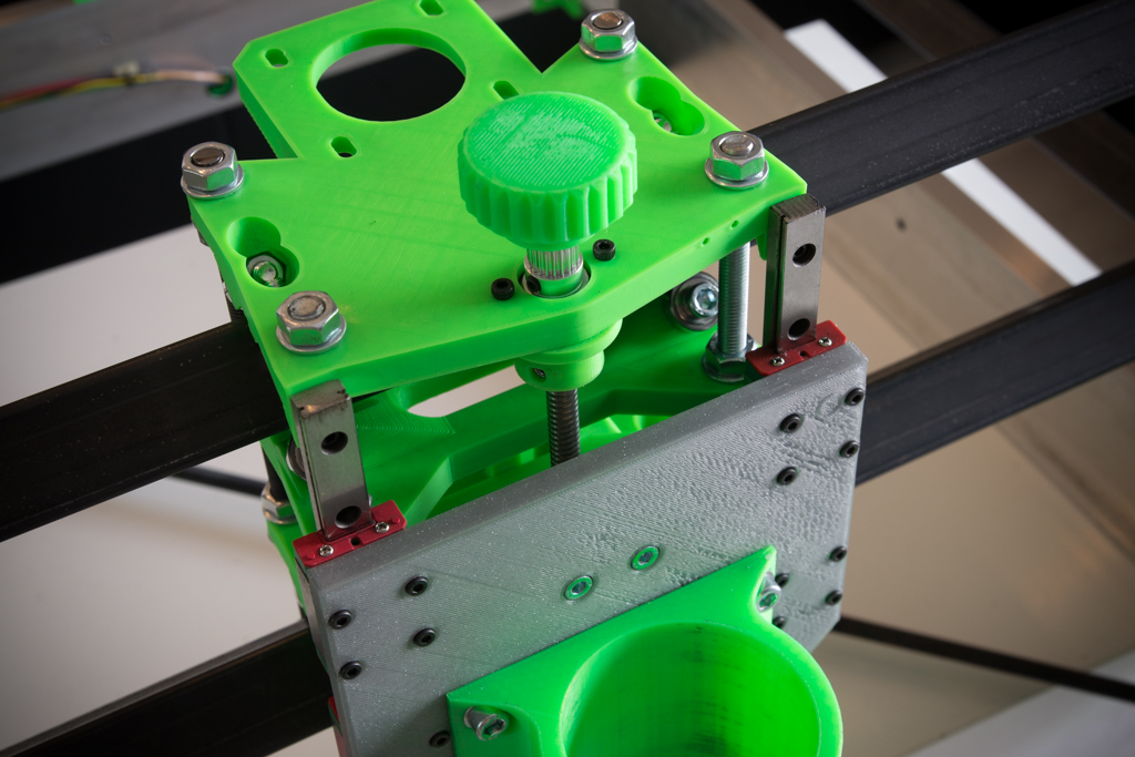
- Prepare the spindle support plate like this:

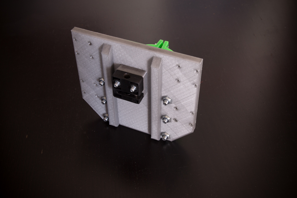
And fix the set to MGN12 bearings
- Take the ACME rod dia 8mm at 2mm pitch
- Prepare it as in the picture
- Insert 2 M4 nuts into the Z locking piece and then two M4 grub screws
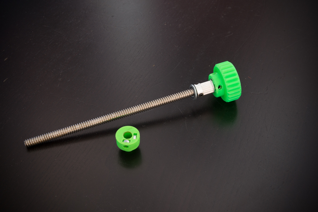
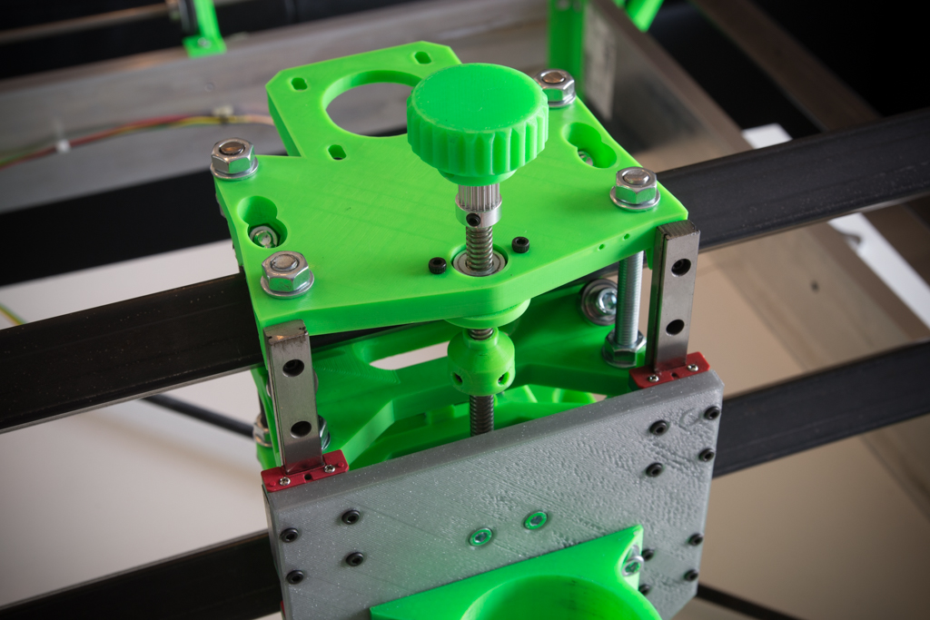
- Thread the rod from above
- Thread the Z locking piece
- Screw the ACME rod a little
- Put the 20-tooth pulley in abutment with the 608zz bearing at the top
- Hold the Z locking piece under the 608zz bearing and tighten it
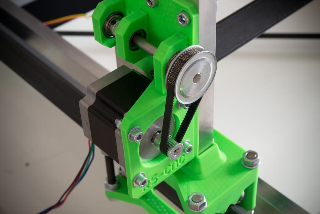
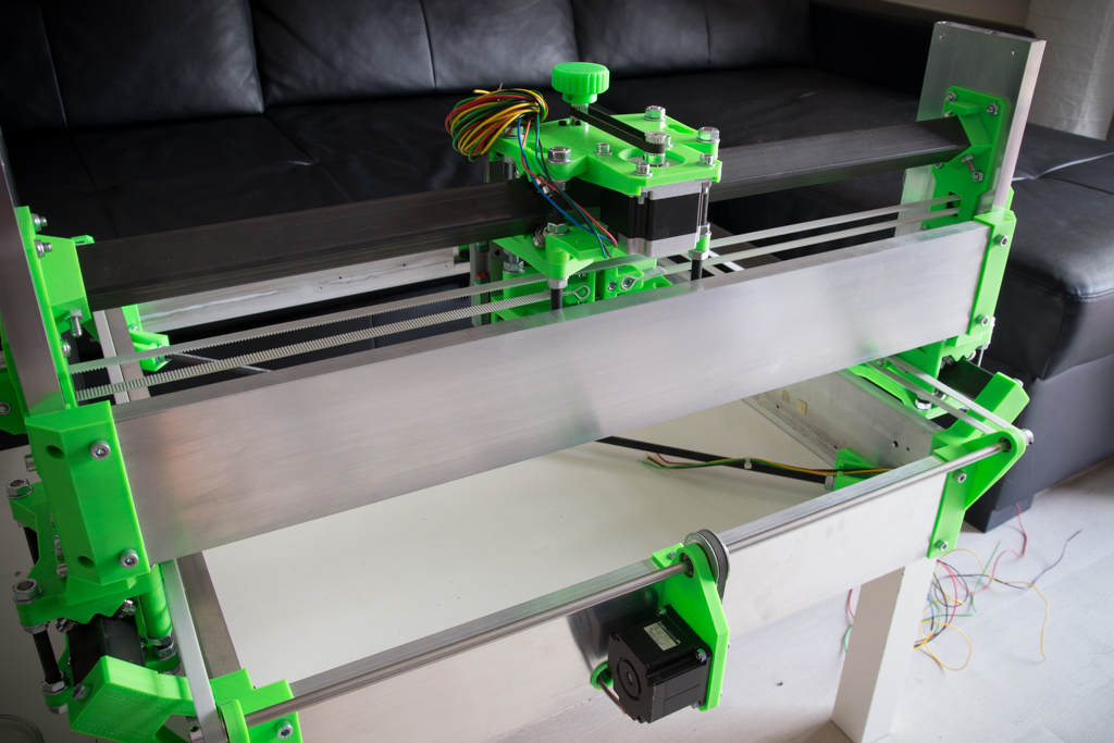
- Mount a Nema 23 in Z
- Fit the belt and tighten
- Tighten the motor screws
- Mount a Nema23 in X
- Fit the belt and tighten
- Tighten the motor screws
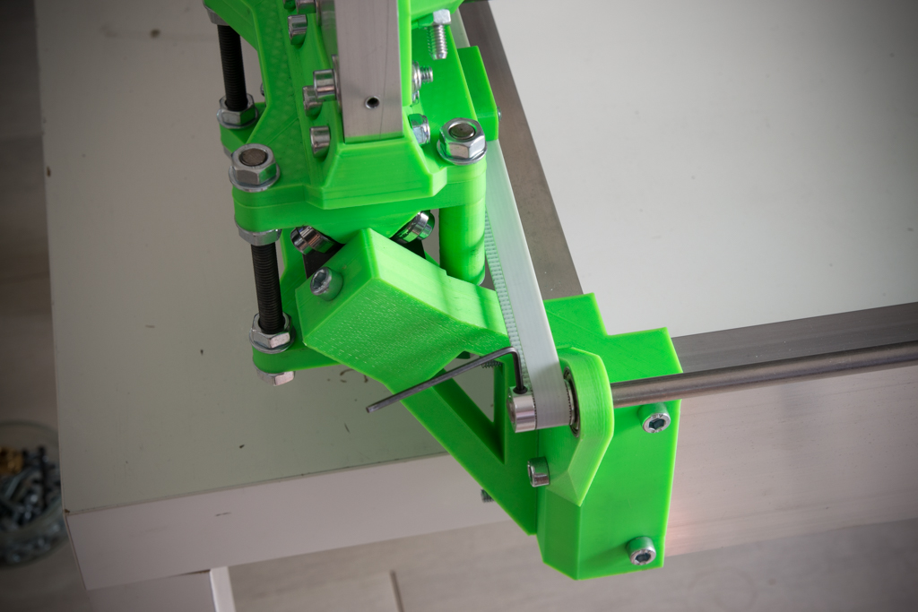
- Fit the 3 large belts of the machine and tension them using the tensioners
- untighten one of the 2 pulleys 20 teeth of Y
- Rear end the two Y-carriages
- Tighten the 20-tooth pulley that was released
- That’s it, your X axis is perpendicular to Y
- Wire the X and Z switches to “normally closed” (NC) (solder one wire to the NC terminal and the other to the COM terminal)
- Mount the X and Z switches on their location using M2x10 screws

- Fix the rear reinforcement using sheet metal screws
- Prepare the upper reinforcement with 24V leds ribbon
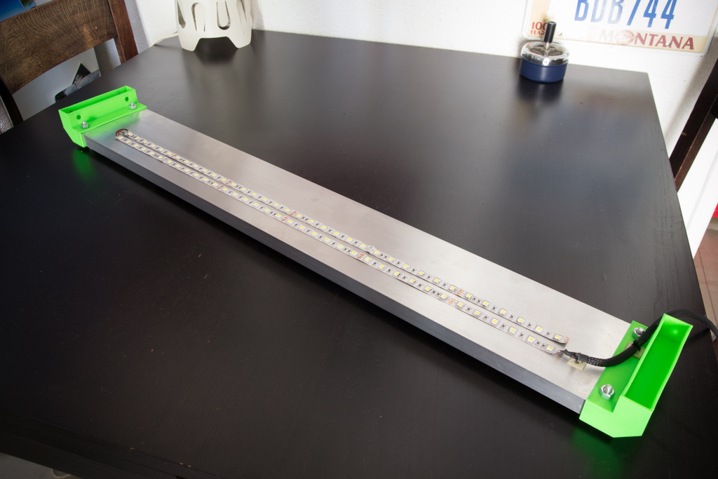
- Screw it
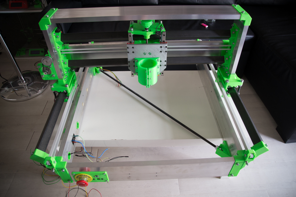
- Install the spindle
- Pass the cables through the X dragchain
- Fix the dragchain
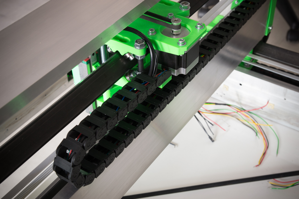
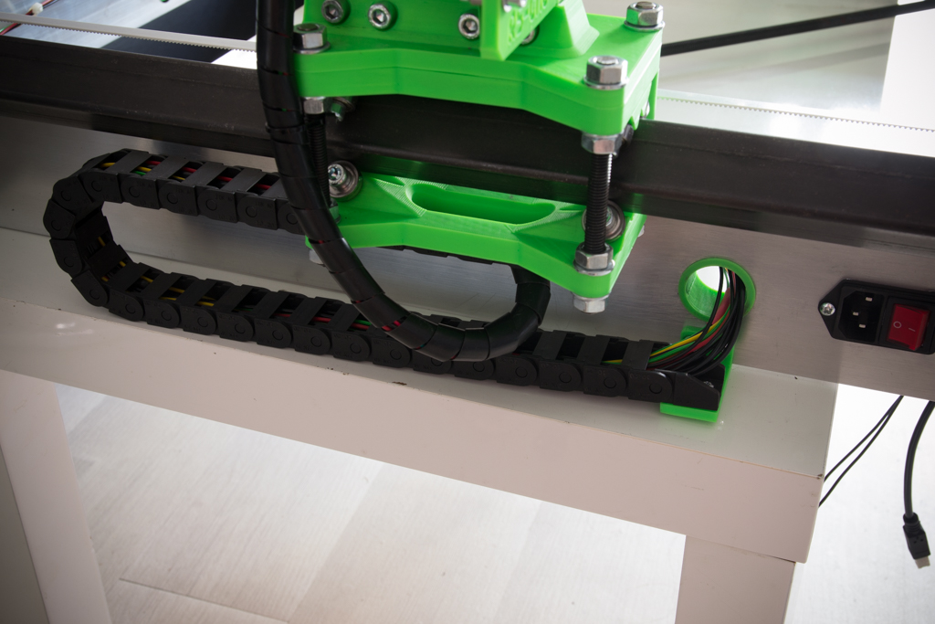
- Pass the cables through the Y dragchain
- Fix the dragchain (There are no pre-holes under the Y dolly_base, you have to make two holes of 2mm yourself)
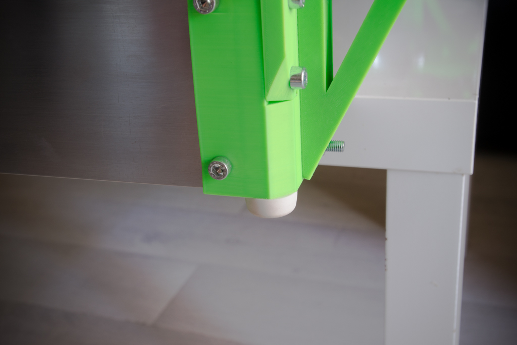
- Screw the rubber feet to each corner
The following is to be done at the end, after wiring, firmware and first tests:
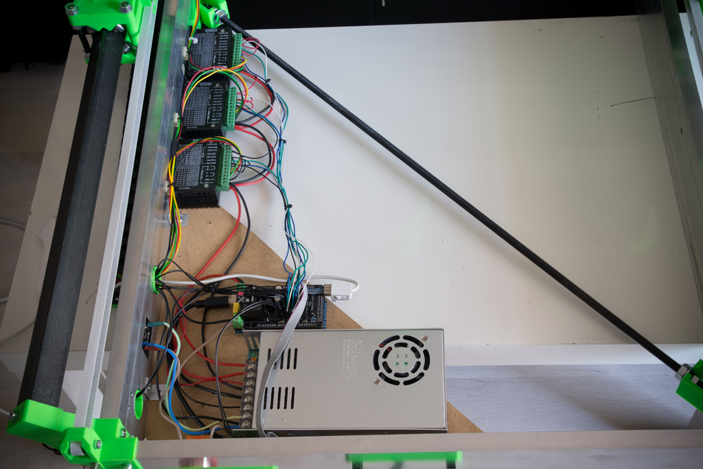
- Example layout of electronics, but do as you want!
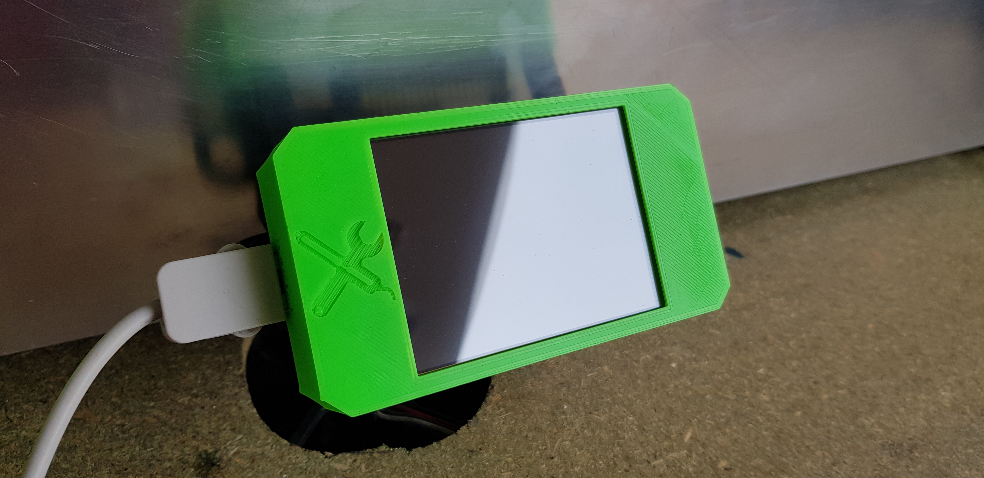
TFT assembly:
- Tape M3 all the holes of the brackets and screw them to the CNC on the holes made on the box screed

- Connect the UART cable connected to the Control board and the USB port cable
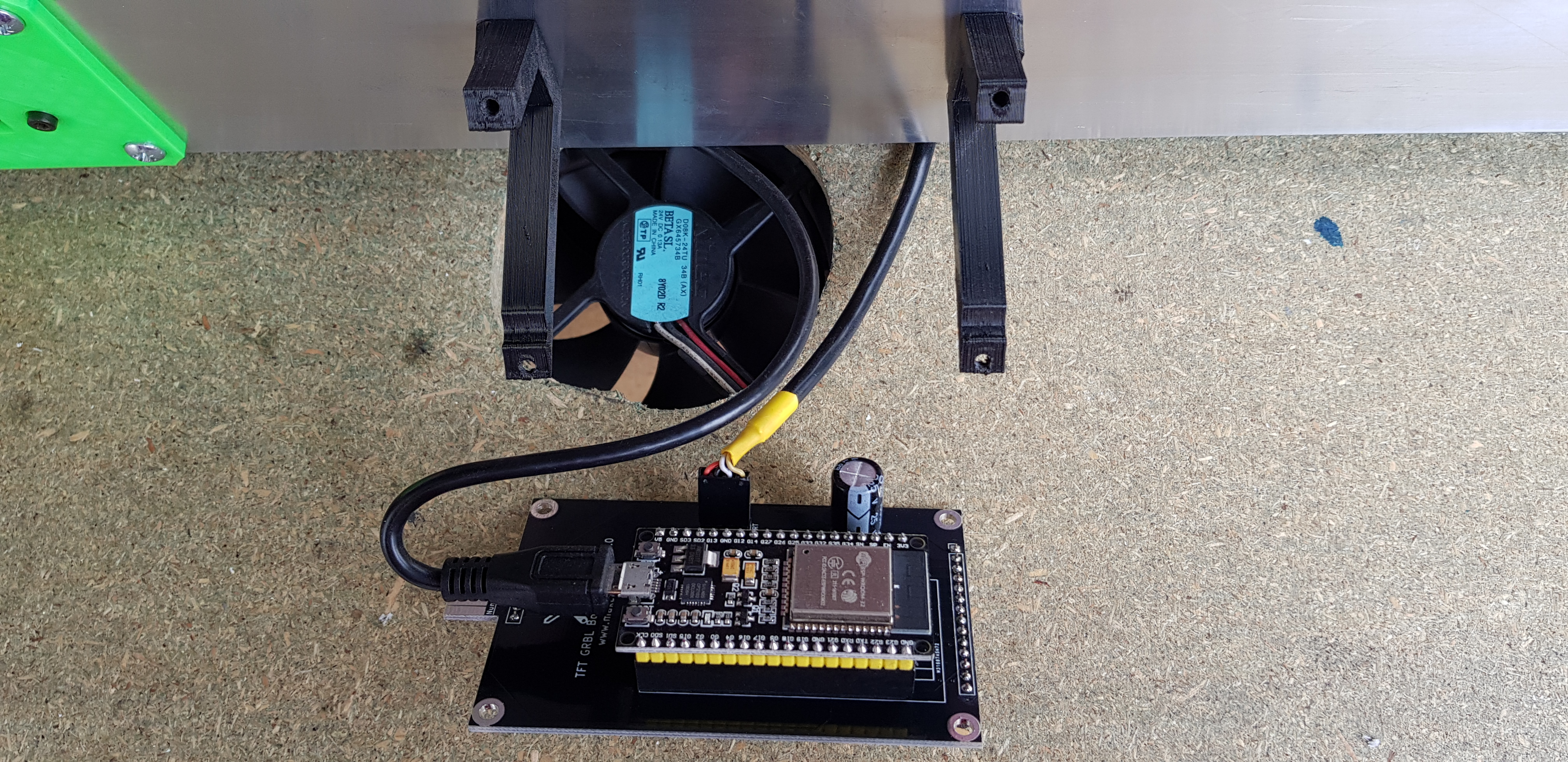
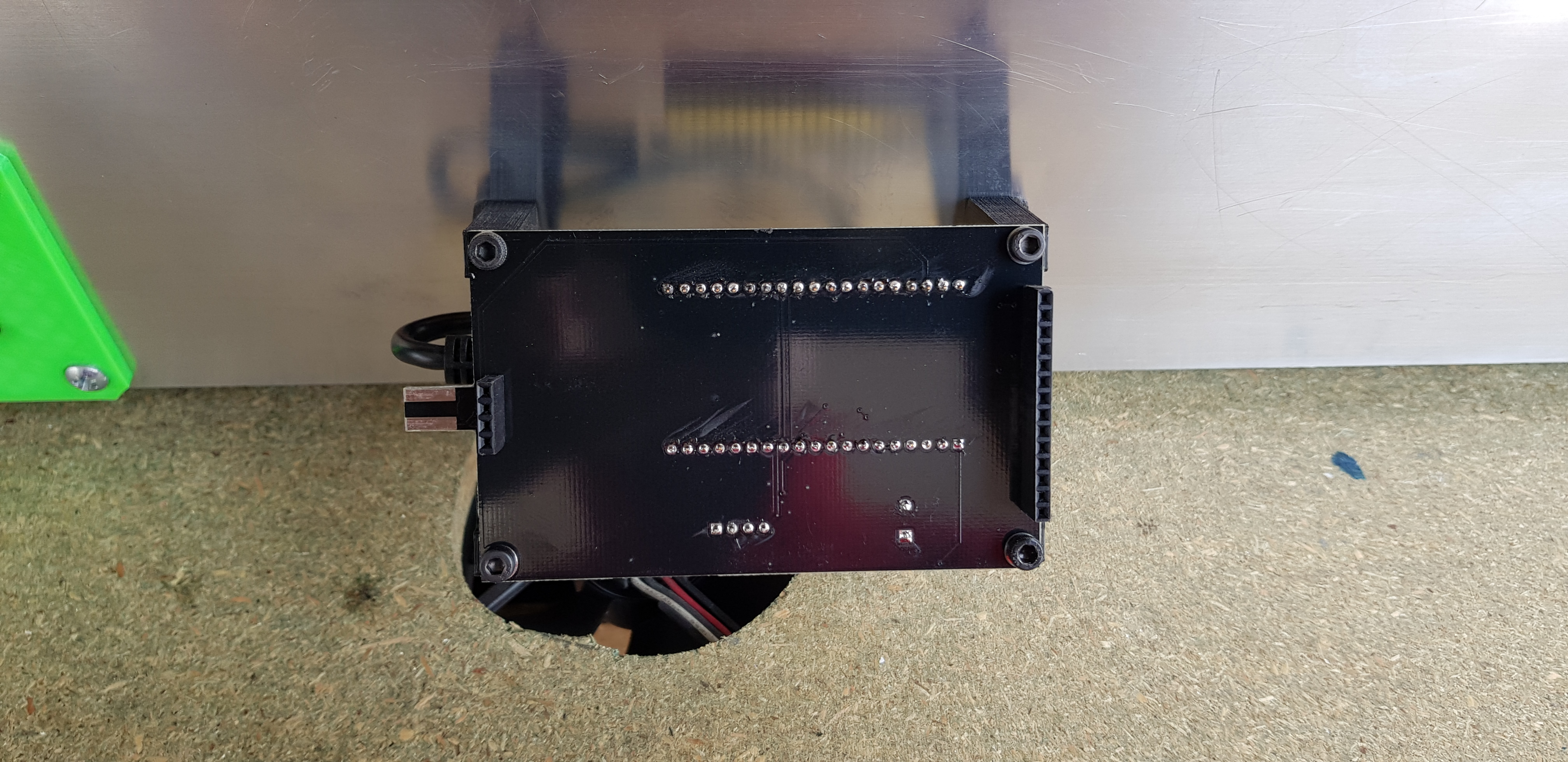
- Screw the TFT board (without the TFT) to the stand
- Plug in the pins header of the TFT on its module

- Press the cover (SD slot down, Nunchuk socket on the left)

- Connect the plug of the Nunchuk (refer to the shape of the plug on the printed cover to make no mistake)
Note: The fan shown in the photos is not there to cool the TFT but for the air flow of my soundproof housing, you don’t need to ventilate the TFT.
Fixing the tray to the machine:
- Put the 6 tray knobs in place
- Put the tray, adjust the height of the 4 corners and tighten the knobs
For the next step: