The I3RS is getting a little facelift, here is the list of modifications:
-
- 32-bit motherboard running Marlin 2.x
- TFT touch screen and Marlin LCD, you can switch from one to the other, it’s 2 screens in one!
- Silent drivers, optional: TCM2208 or TMC2208UART or 2209UART
- Double gear drive for better filament grip
- The fan duct has been touched up so as not to blow on the nozzle
- The BLtouch support has been lowered by 1mm to avoid having to put thick washers in certain cases.
Printable parts
Here are the parts to print for the update: Printable parts
| Nom | Quantité | Infill | Commentaire |
|---|---|---|---|
| BLtouch_Holder | 1 | 20/30% | ABS/PETG |
| Extrud_A | 1 | 20/30% | ABS/PETG |
| Extrud_B | 1 | 20/30% | ABS/PETG |
| Extrud_Idler | 1 | 20/30% | PLA/ABS/PETG |
| Fan_Duct | 1 | / | ABS/PETG |
| SKR_box | 1 | / | PLA/PETG |
| SKR_box_cover | 1 | / | PLA/PETG |
| TFT35v3cover | 1 | / | PLA/PETG |
| TFTholderA | 1 | / | PLA/PETG |
| TFTholderB | 1 | / | PLA/PETG |
Parts list:
| Nom | Quantité | Commentaire | Lien |
|---|---|---|---|
| Carte mère SKR V1.4 avec 4 drivers TMC2209 | 1 | choisir "Taille: With TMC2209x4 " puis "Couleur: SKR V1.4" | Aliexpress |
| Ecran TFT35 V3.0 (version avec le bouton à droite) | 1 | Aliexpress | |
| Kit engrenage double type Bondtech | 1 | Aliexpress | |
| Roulements MR105RS | 2 roulements | Aliexpress | |
| Paire de nappes IDC 10 pins 60cm | 1 paire | Car celles fournies avec le LCD sont trop courtes (choisir 60CM) | Aliexpress |
| Rallonge pour le cable TFT | 1 | Car cable d'origine trop court (choisir "4S" pour 5 fils) | Aliexpress |
New parts assembly :
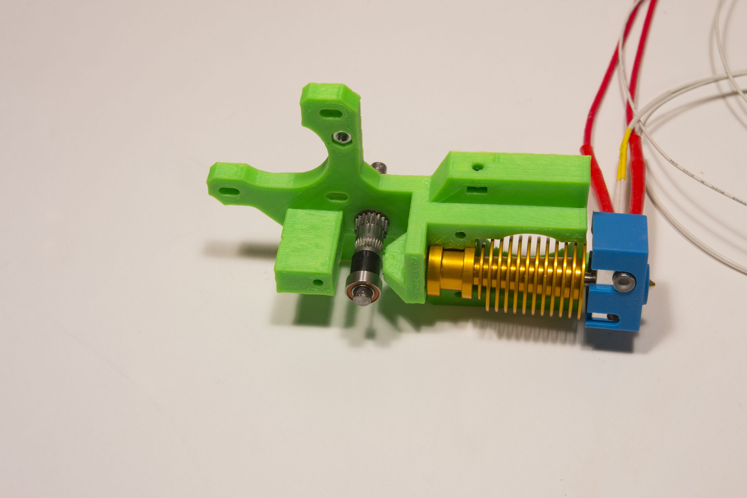
Extruder assembly
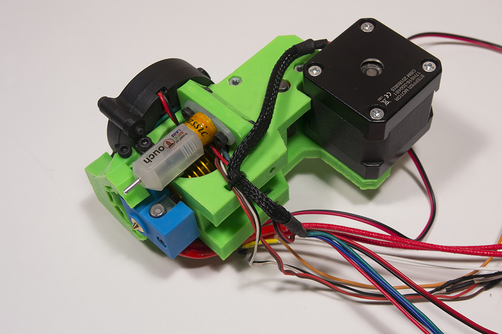
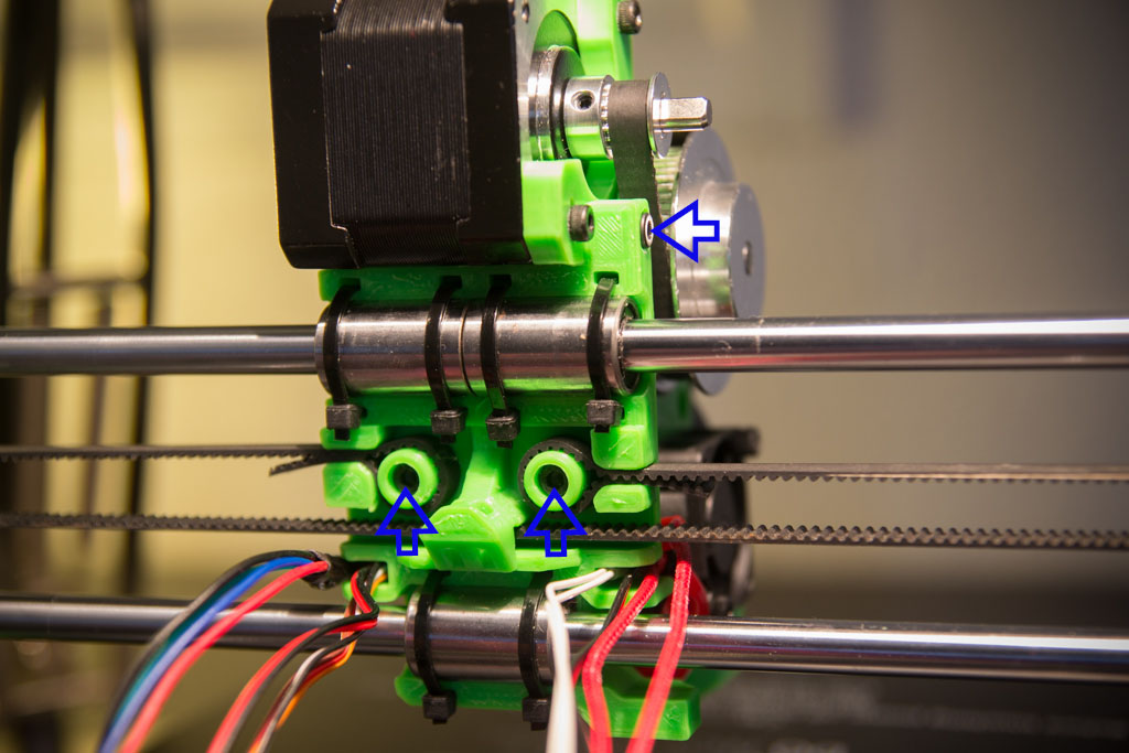
We insert M3 nuts in all the locations indicated by blue arrows
The two square nuts supplied with the double gear are inserted at the yellow arrow.
We tap the hole on the side indicated by the purple arrow
We thread the gear on needle cages in the flap of the extruder and we slide its axis provided with. (Red arrow)
We screw the BlTouch to its support
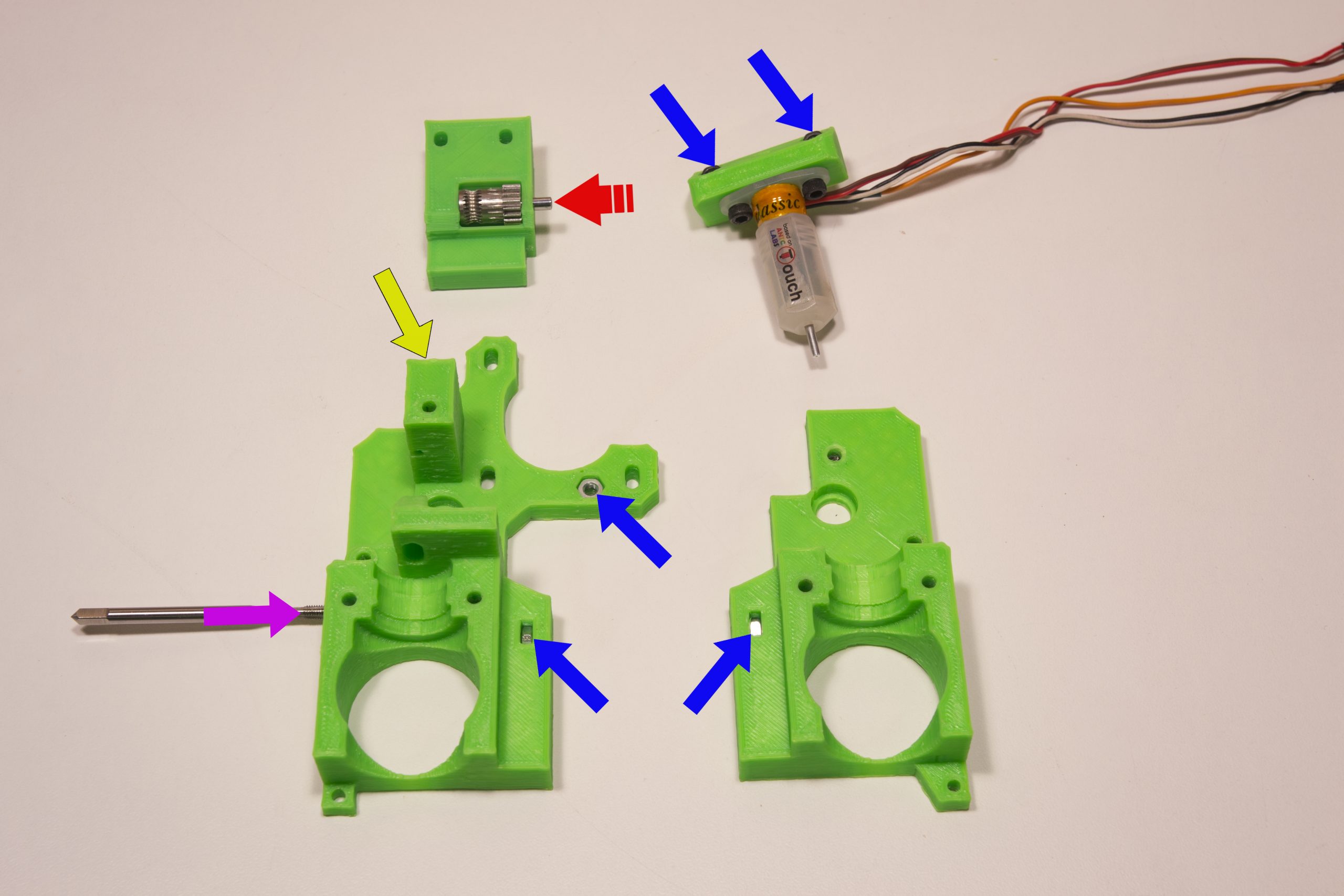
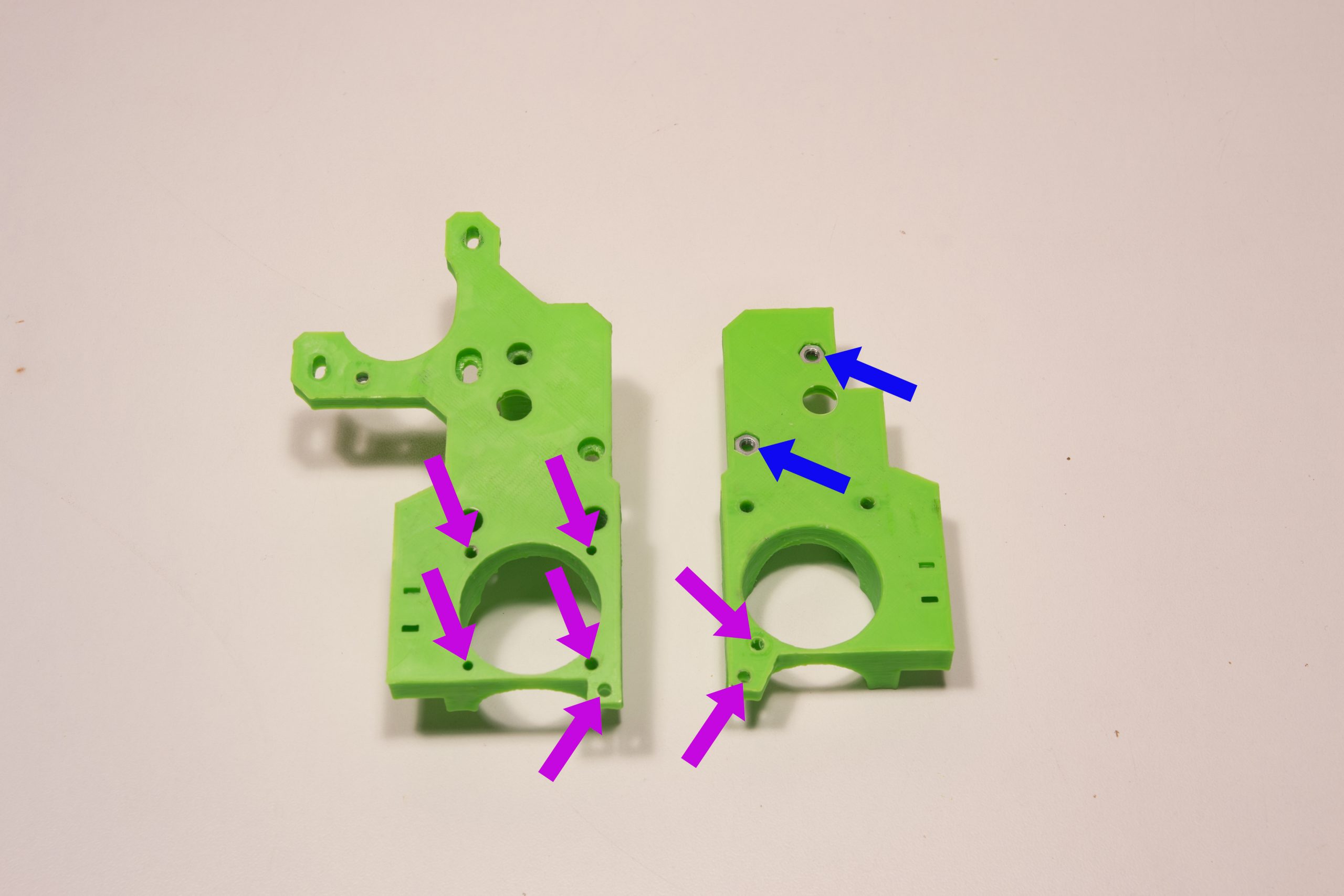
M3 nuts are fitted in the slots marked with the blue arrows
We tap M3 the holes indicated by the purple arrows
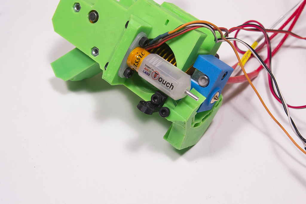
We cut about 50mm of PTFE tube which we push into the heating head
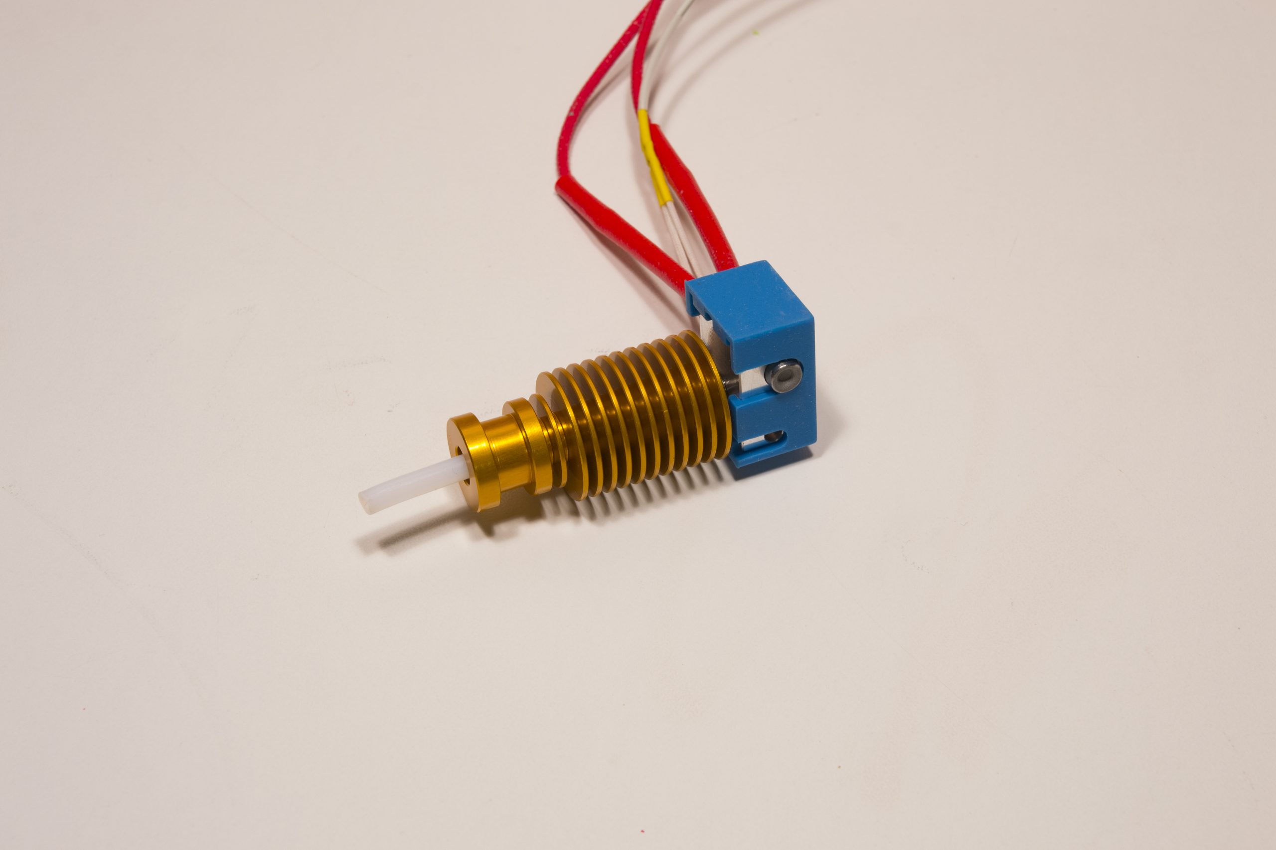
We put everything in half of the extruder and we cut the PTFE which exceeds

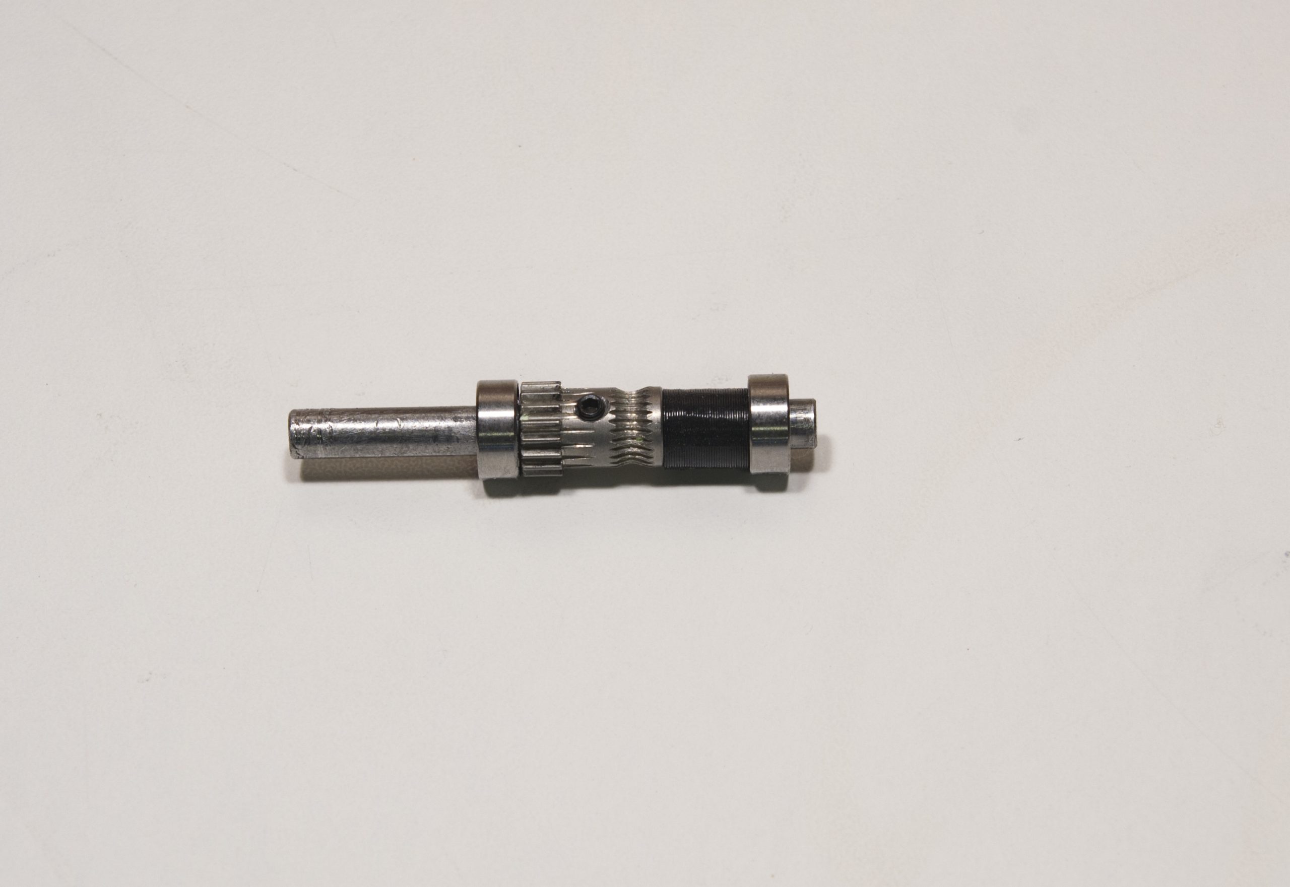
The axis is prepared by threading the drive gear, the printed spacer, and the two MR105RS bearings like this (do not tighten the screw yet) (It is strongly recommended to file a flat on the axis, just under the screw of the filament drive gear).
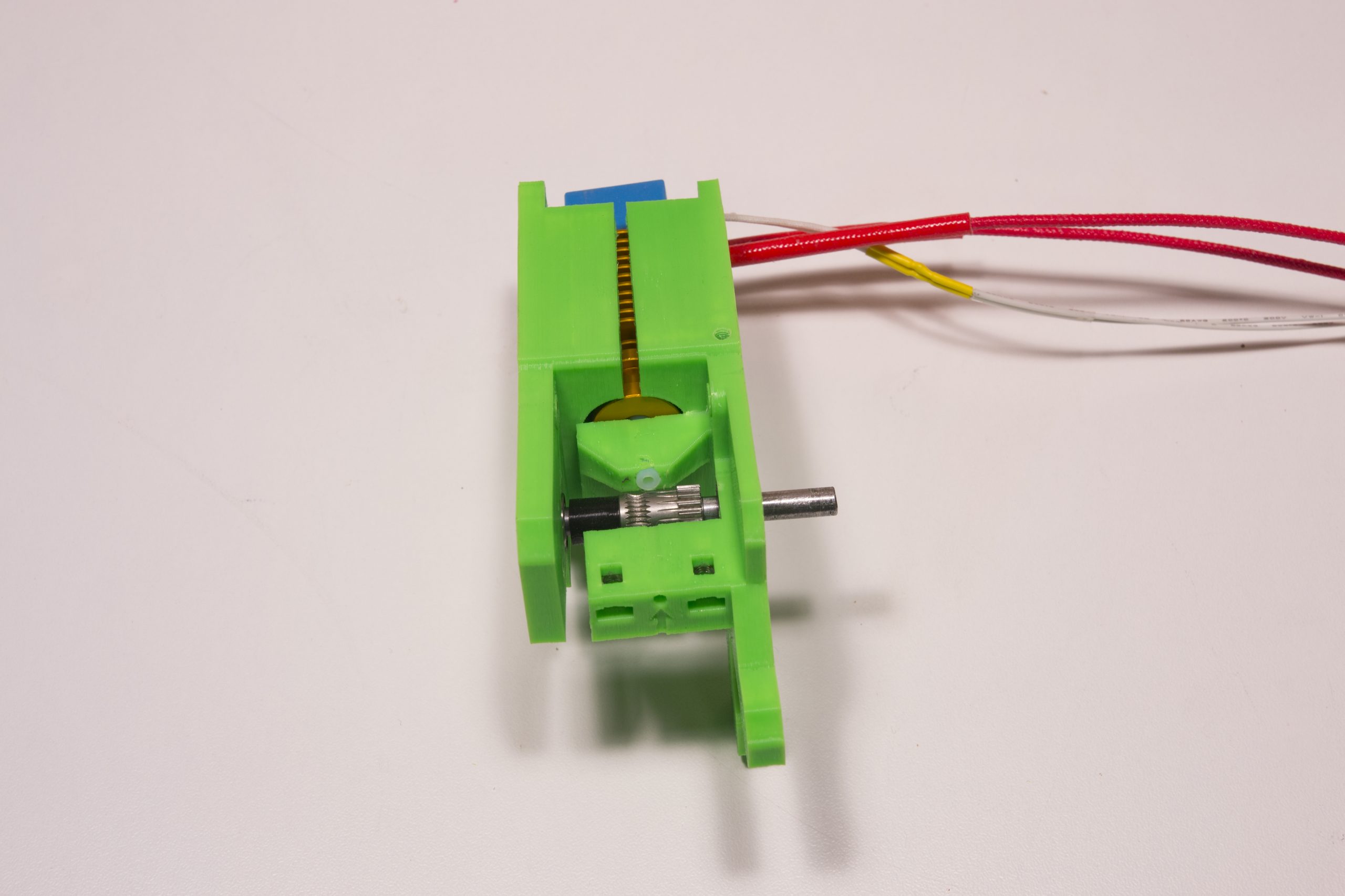
We put everything in place in this direction
We put the second half
We put two M3x30 screws through the extruder which are screwed on the BlTouch support.
Wait until all M3x30 screws are in place before tightening

Add the extruder idler, and tighten all the screws
We put the 5mm axis flush with the plastic part on this side and we screw the drive gear firmly

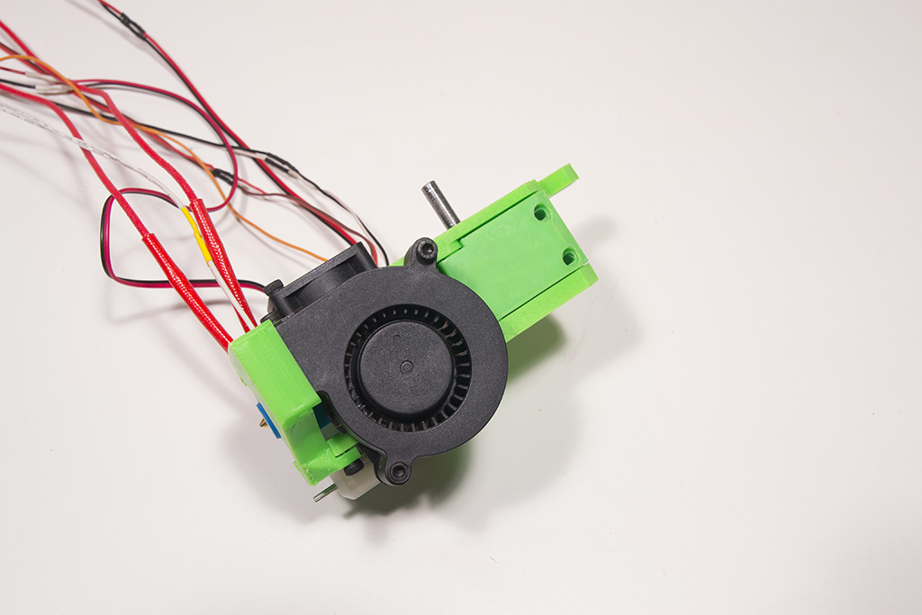
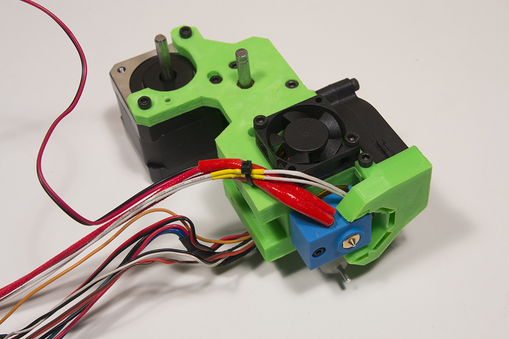
We screw the fan with two M3x16 screws, the fan must blow inwards, so the fan label must be inwards.
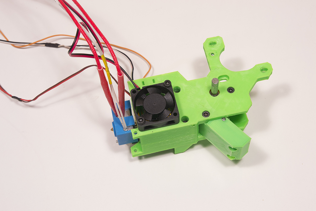
The fan duct is fixed with two M3x6 screws

We screw the small part of the radial fan support with an M3x6 screw and tap the other hole M3.
The radial fan is fixed with two M3x20 screws
We put the M3x16 screws on the extruder idler and we can tighten
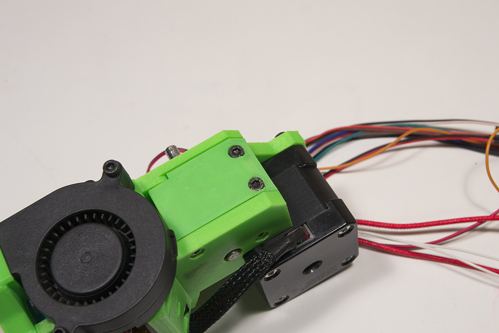
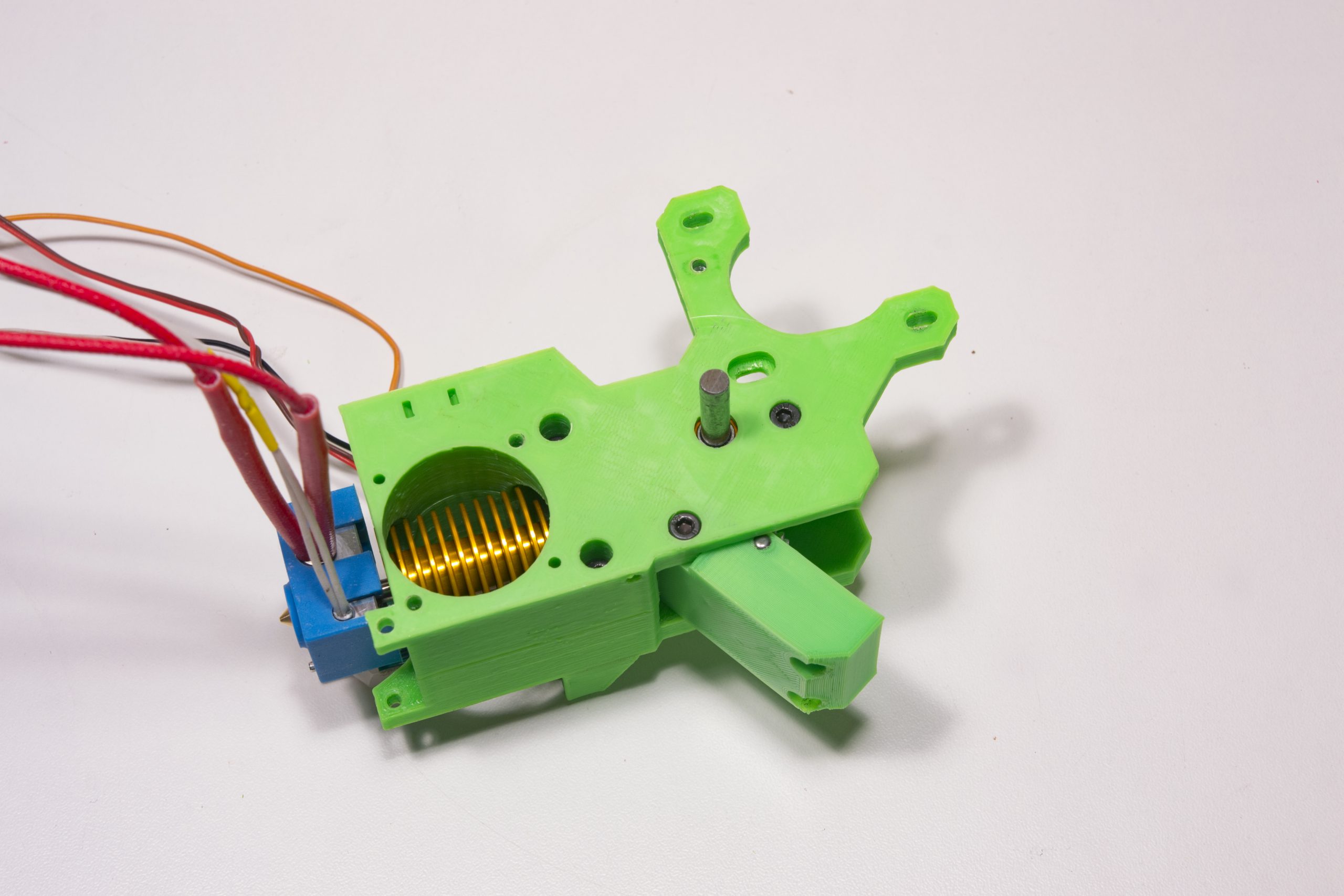
We now screw the motor, the motor cables must be facing forward.
The small motor fixing screw in the middle must be coated with thread locker and must not be fully tightened.
Zip the cables to the extruder on each side thanks to the zip passages provided for this purpose. (Be careful not to tighten the zips too much because the BLtouch cables are very fragile!)
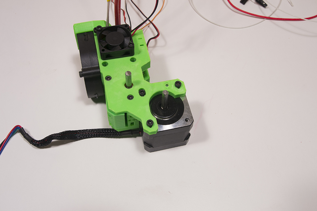
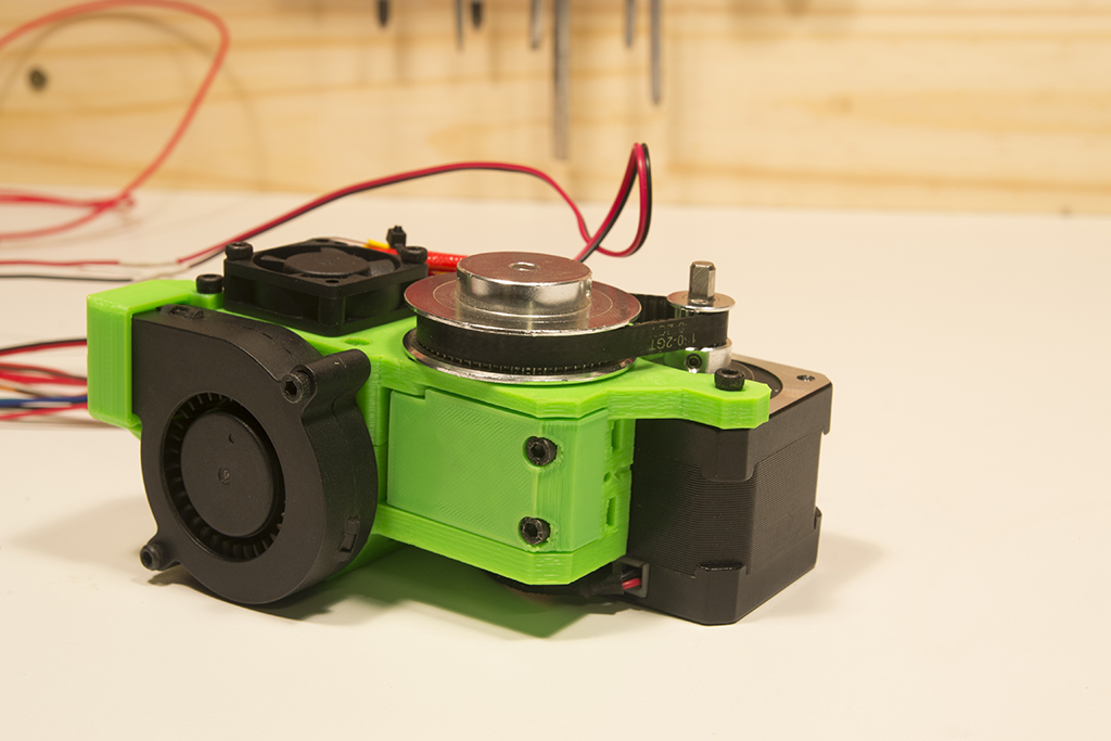
take the pulley 60 teeth, the 16 teeth and the belt 150 and push the assembly on their axis
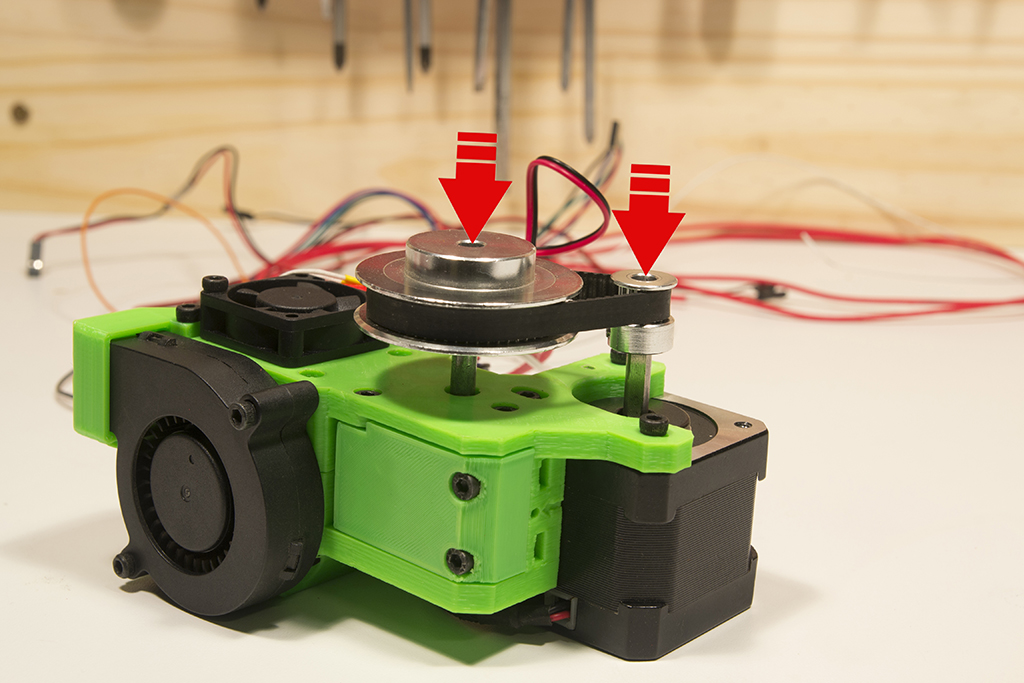
The 16-tooth pulley must not be in abutment against the motor and the 60-tooth pulley must not be in abutment on the extruder, leave a small space and tighten everything
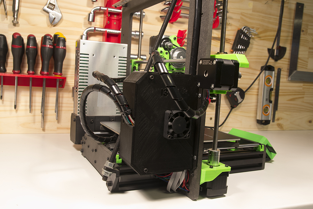
We fix the extruder on the X carriage with two M3x20 screws and an M3x10 screw on the side (blue arrows)
Extend the fan cables
Zip all cables together
TFT assembly
Take the two pieces of TFT support and thread them like this
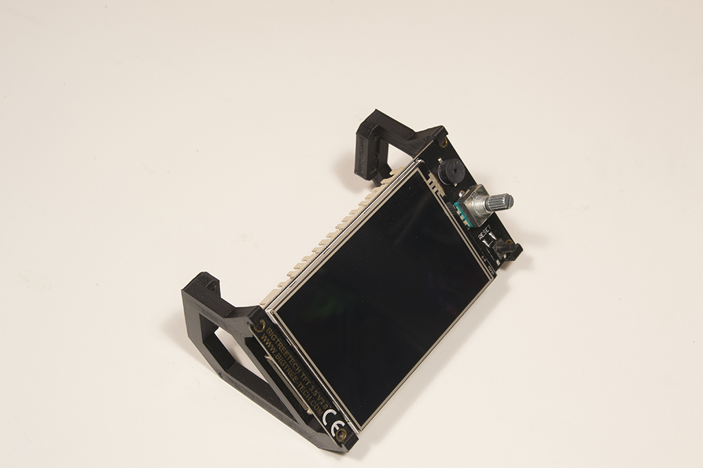
Put on the cover and the button
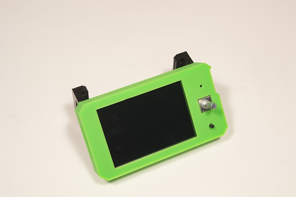
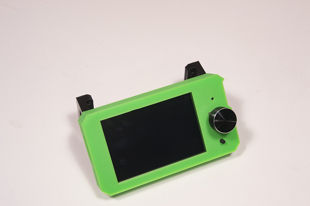
and screw everything to the frame with 4 M3x16 screws

Electronic box
Tap M3 all holes indicated by arrows

Screw the box to the frame using 4 M3x10 screws

To simplify the continuation, already connect the power cables and the heating plate (see next page, wiring) then screw the board in the box.
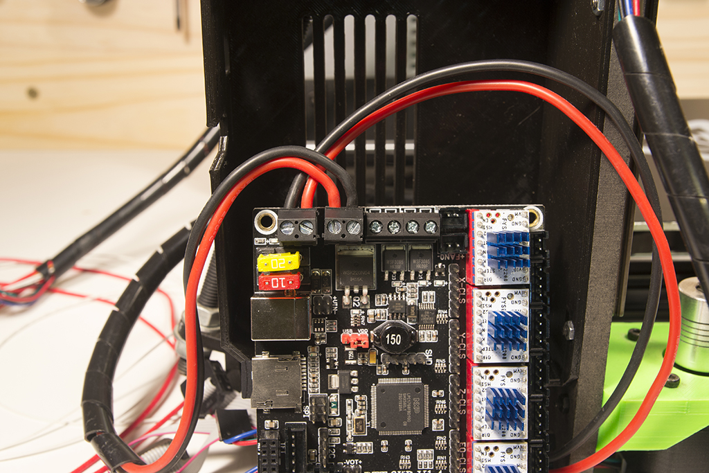

Screw the 40mm fan to the housing cover with 4 M3x16 screws

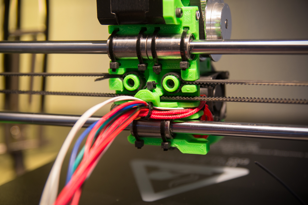
Rear view when all cabled and cover closed:
Go to the Wiring