Pics of Romaker, videos of Woodreff (a big thank you to him)
Before starting the assembly, I just want to give two three tips for cutting and drilling parts.
Drilling:
- Place the plastic part or printable template on the part to be drilled.
- Using a pencil or a tip, draw the holes to be drilled on both sides of the mason box screed so that the holes are facing each other.
- Remove the template or plastic part
- It is pointed with a needle
- Drill with small front hole (3mm) before drilling to 6mm or more.
Aluminium box screed cutting (It goes of the final geometry of your CNC!):
- Observe precisely the measures
- Draw the cutting line with a square, and on both sides!
- Recheck the measurement after cutting, deburring and filing if necessary.
To tighten the screws through the box screed, go quiet, don’t crush the aluminum, a light tightening is enough, put brake nuts or a drop of brake net. If you really want to squeeze like crazy, you can clap 15mm MDF in box screed ! Personally I have not put and it does not move once the editing is finished, it is not a question of strength but geometry;)
We can start 🙂
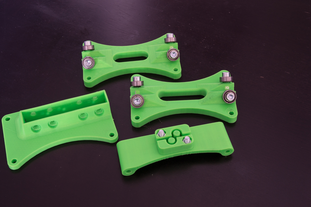
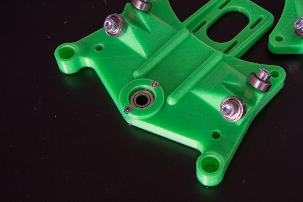
Take the 4 printable corners and mount them like this with 2 bearings 608zz and the four 625zz
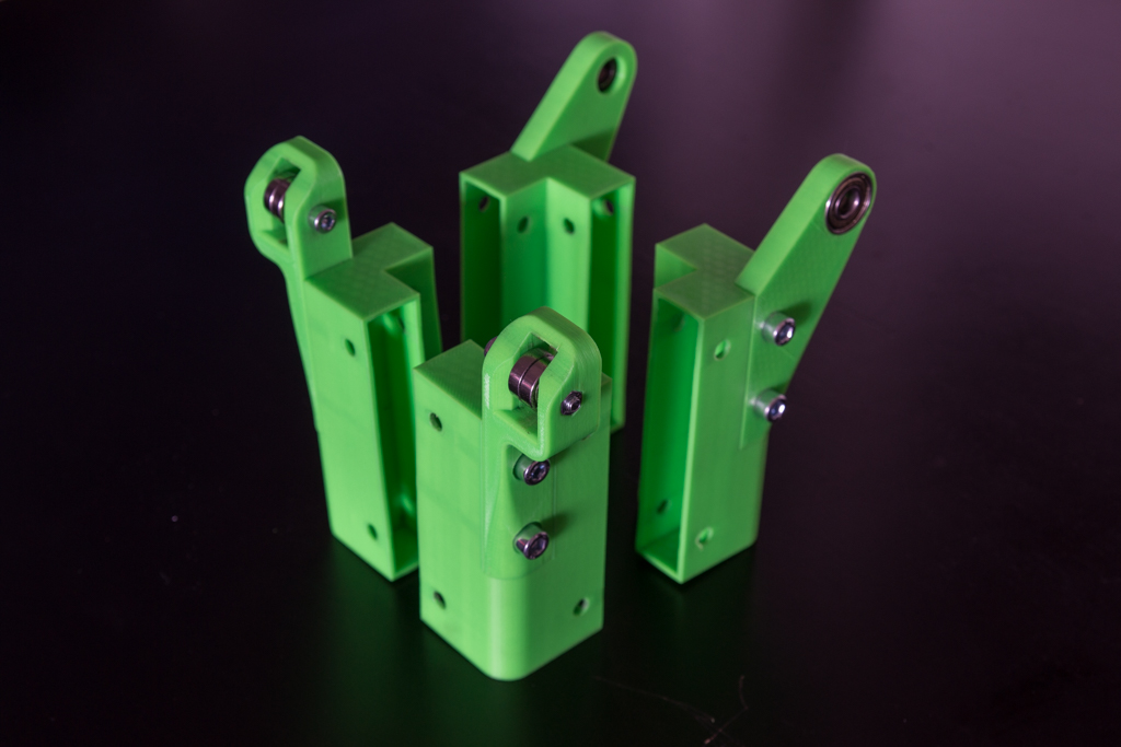
Then screw the rubber door pads into the hole provided for this:

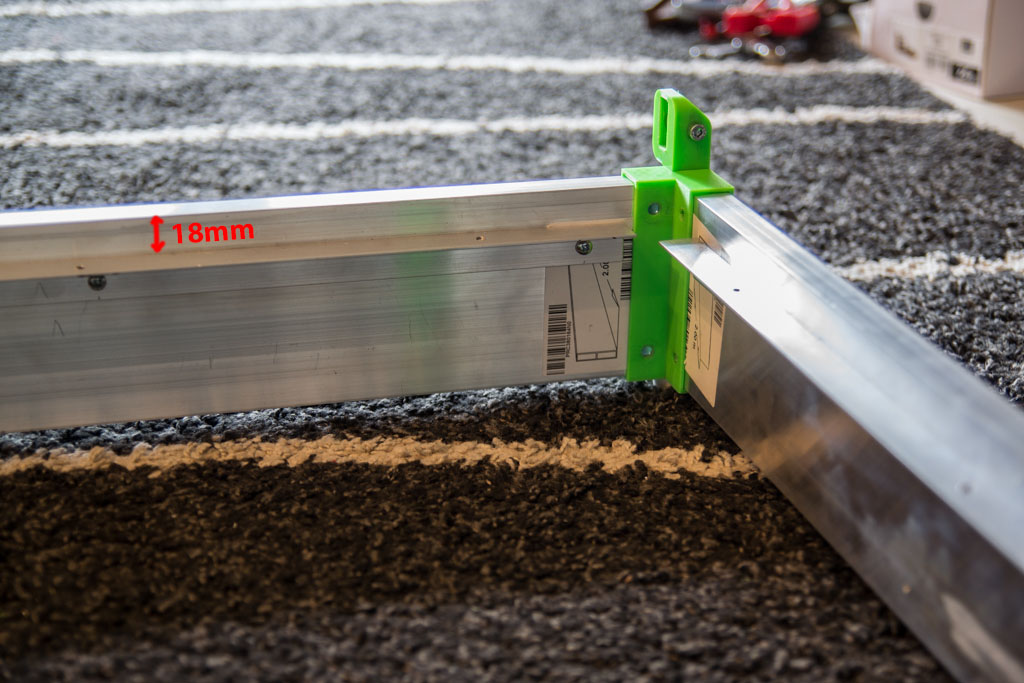
Take the 600mm and 750 mm box screed and mount the blanks just to draw the holes, push the parts thoroughly, debug and drill the holes.
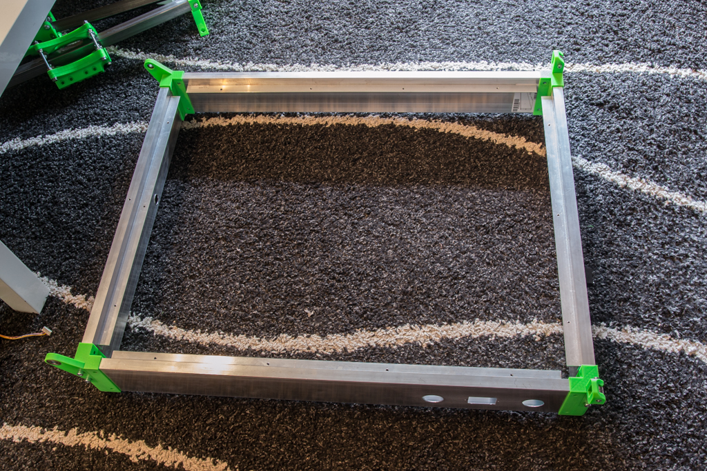
Drill and screw with sheet metal screws on the inside perimeter, 18mm from the top. You can drill holes 1mm wider than the diameter of the screws to adjust the tray at the end. (Do not drill the top holes yet)
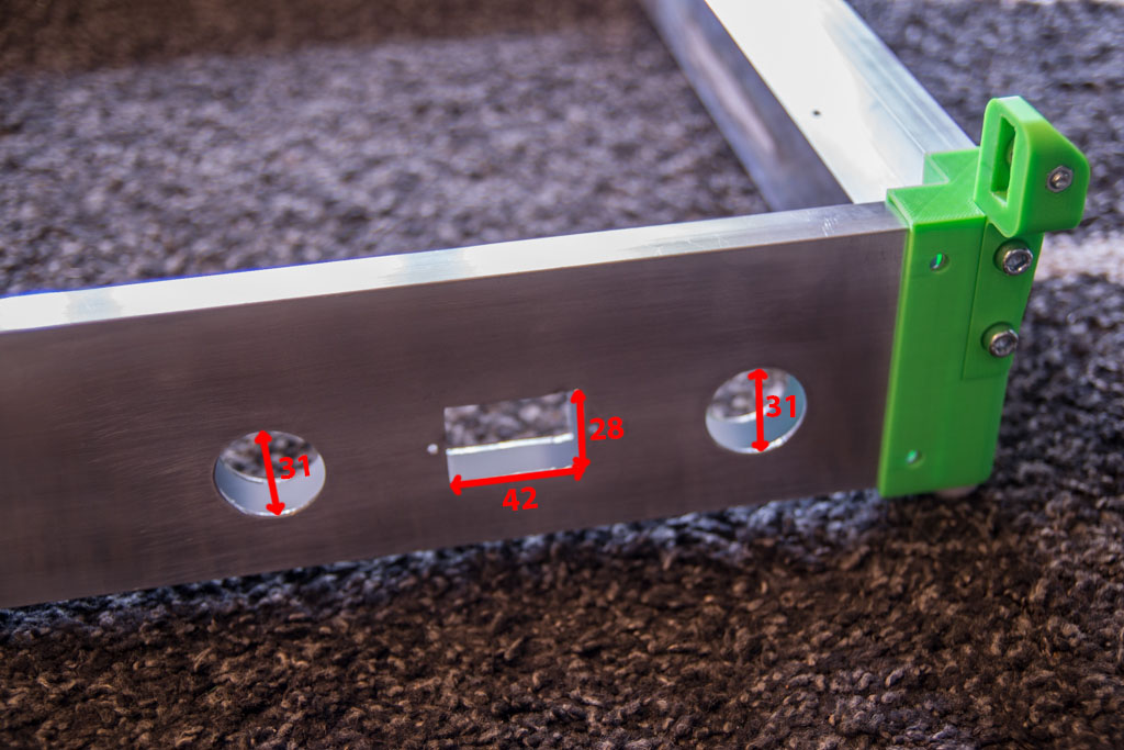
Drill as in the pictures, the holes are made with the 31mm bell saw and the rectangle with two holes in each corner of the rectangle then jigsaw and metal file. Do not screw the corners yet.
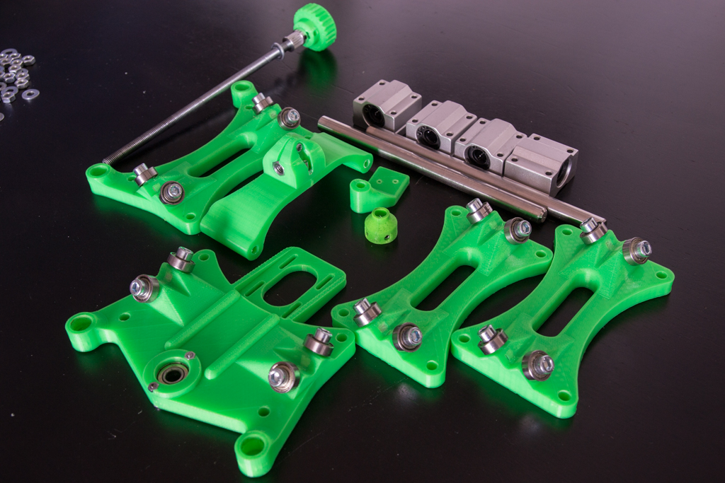
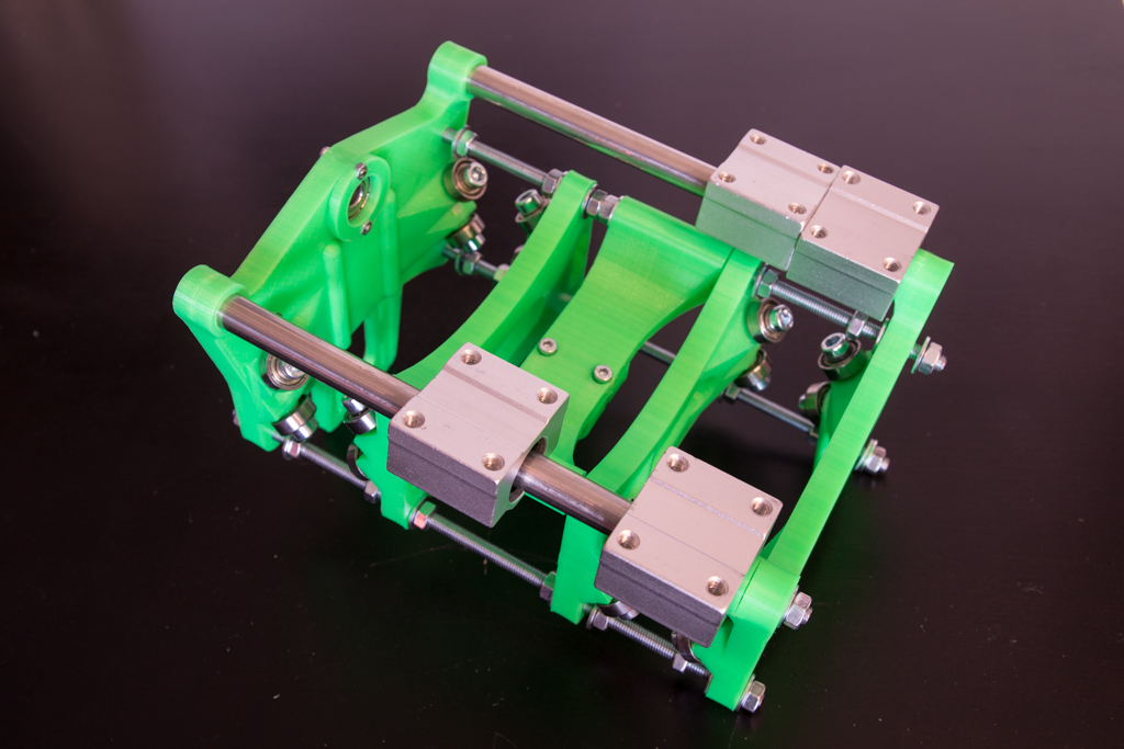
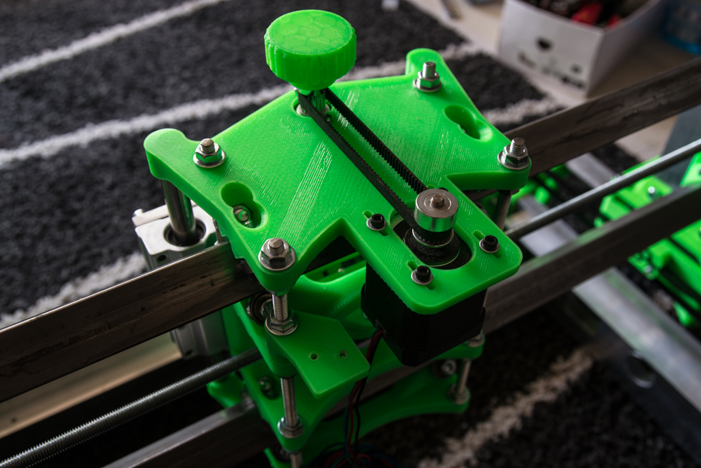
Y dolly Assembly
Mount the 606zz bearings with the 6×20 screws and mount the belt blocker.
And we assemble this way with the rods M6x92, attention to the direction of the parts

Do not tighten the nuts yet.
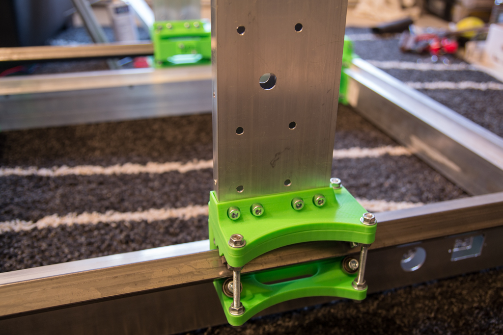
Take the square tube 746mm, nest the supports at the ends, transfer the holes, point, drill, reassemble.
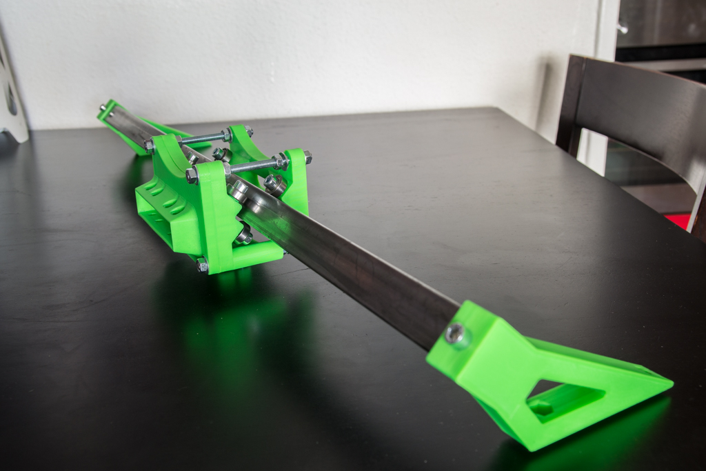
And do the same in symmetry!
Voilà, You can mount the Y brackets on the corners, put the screws and tighten (reasonably said!)
You can tighten the carriage nuts, check that each bearing is in contact with the square tube, the carriage must slide with a very slight resistance. Too tight it will force, not tight enough we risk the game.
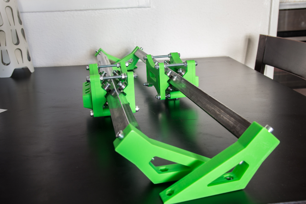
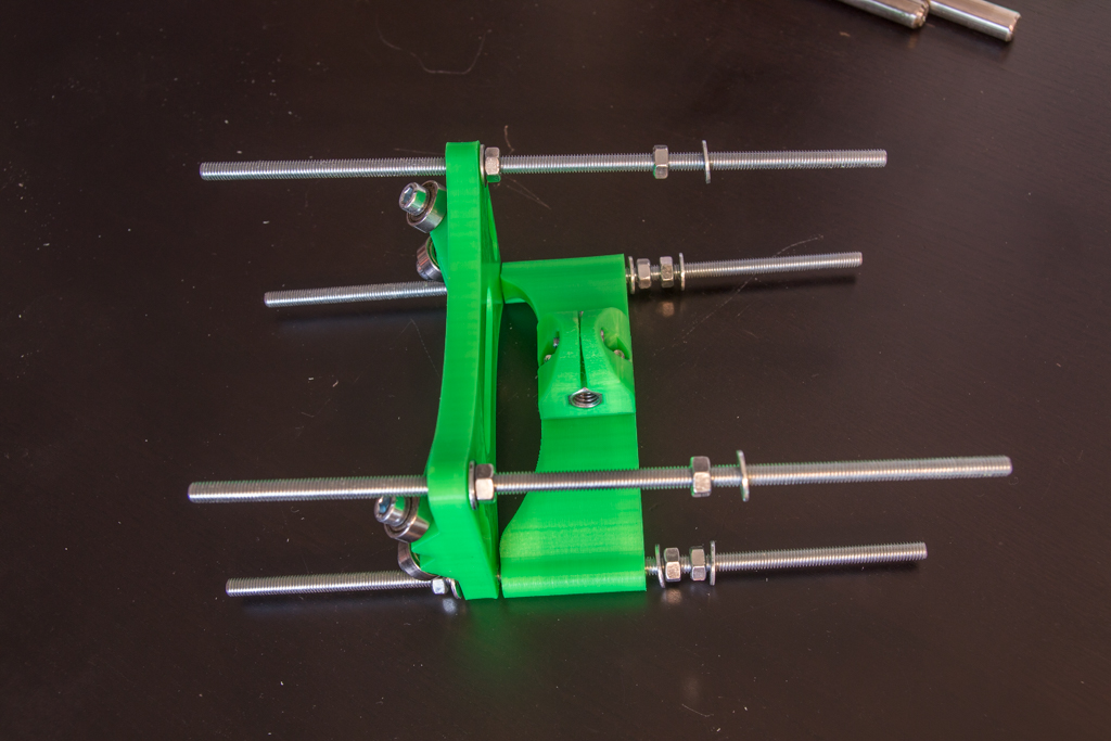
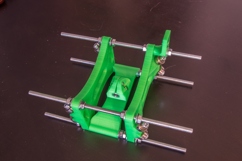
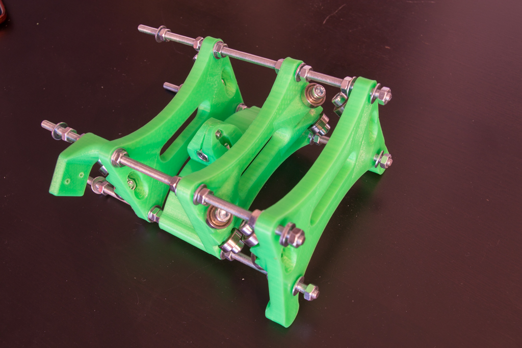
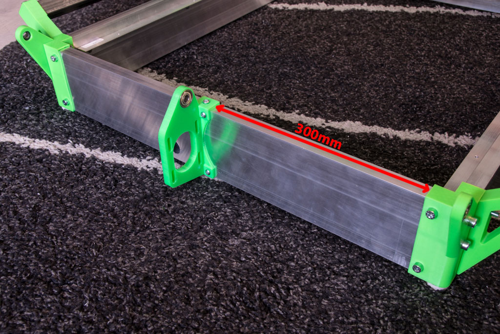
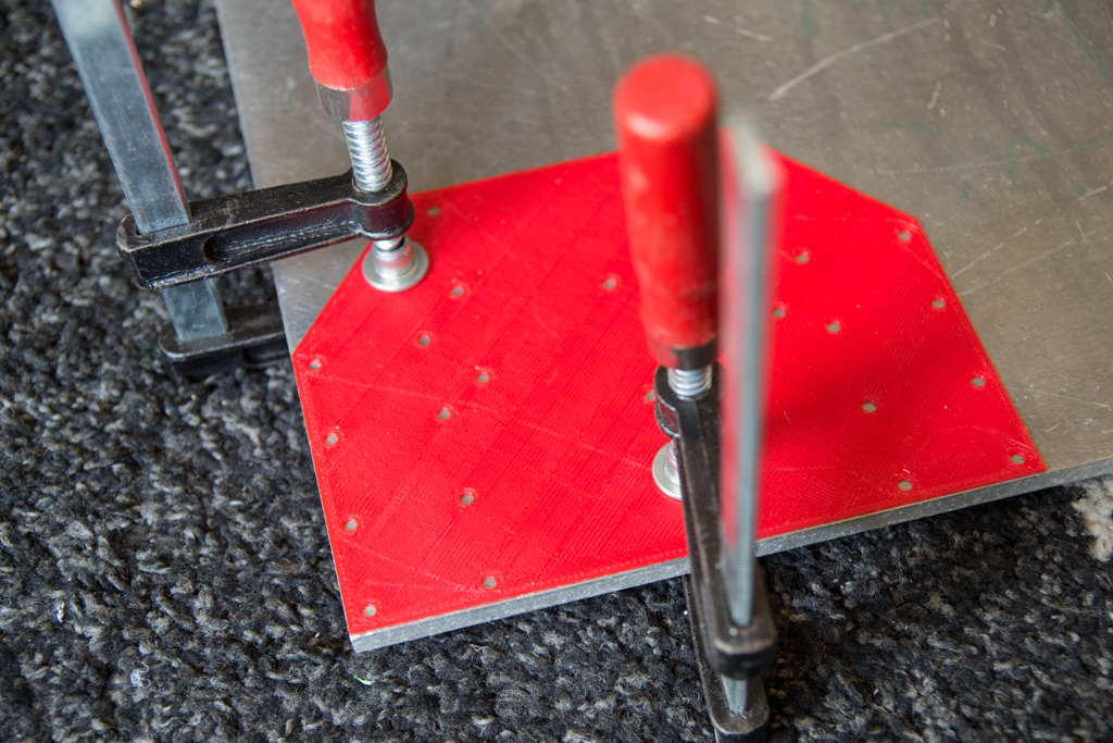
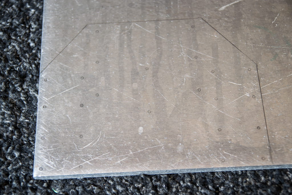
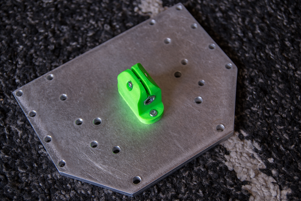
Take the 266mm box screed, nest them in the base of Y, put the drilling template at the bottom and on the side, make it hold with clamps, then you carry the holes of the red piece and the green piece … and we do the same on the other side of the same box screed and the same for the other … Again, pay attention to the meaning. All the holes are drilled to 6mm except the central hole of the red piece will be drilled to 12mm.
And we raise the whole after drilling
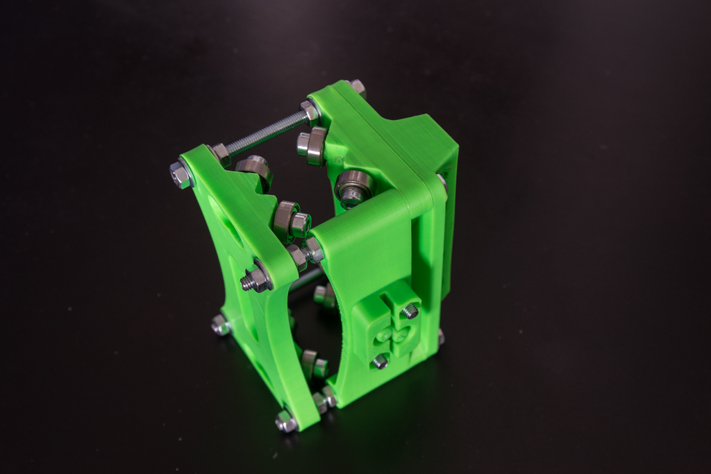
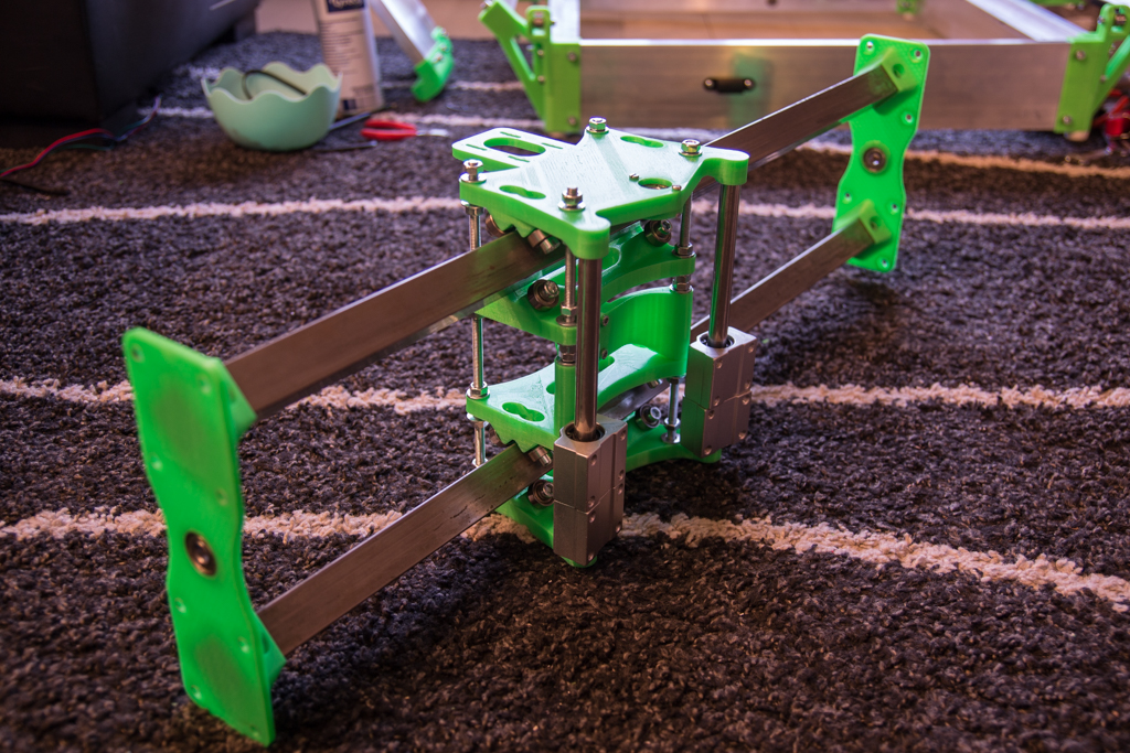
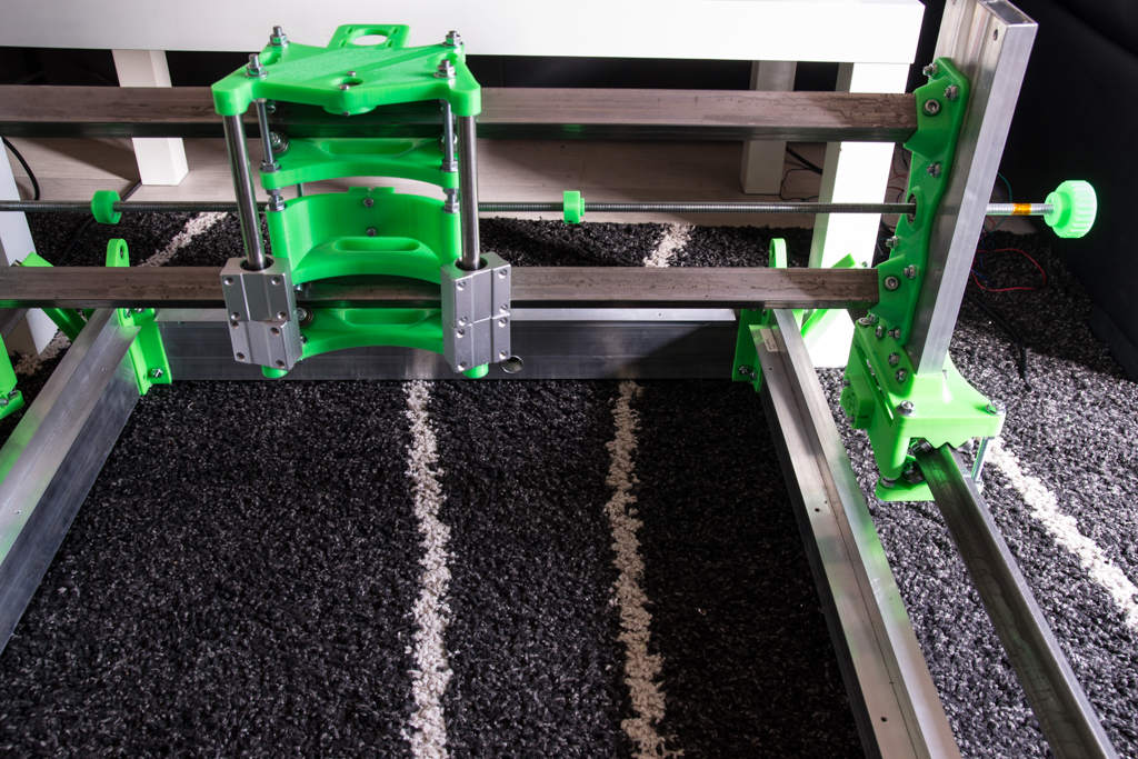
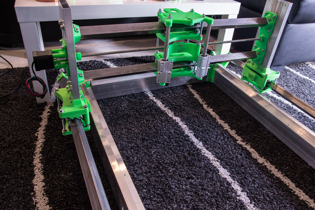
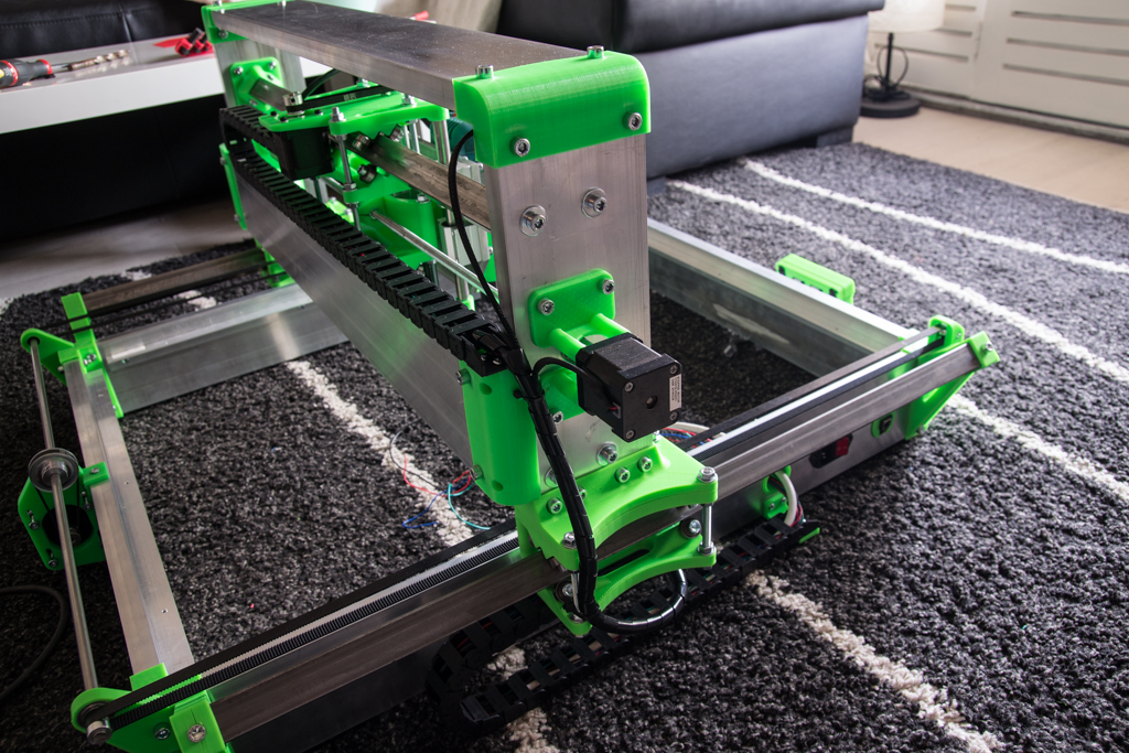
X/Z module assembly
Screw all bearings and “Xnut”.
Put the 608zz bearing and the part that blocks it.
Take the M6x218 threaded rods and follow the steps (pay attention to the direction)
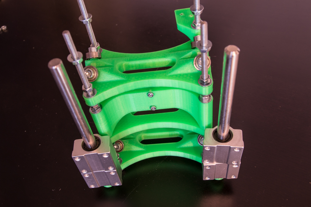
Do not tighten the nuts yet.
Take 702mm square tubes, nest them in their bracket, transfer the holes, debug, point, drill and reassemble one side, insert the X / Z block and nest the bracket at the other end.
Mount a Nema 23 on its bracket (yes it’s a nema17 on the pics, that’s a old version)
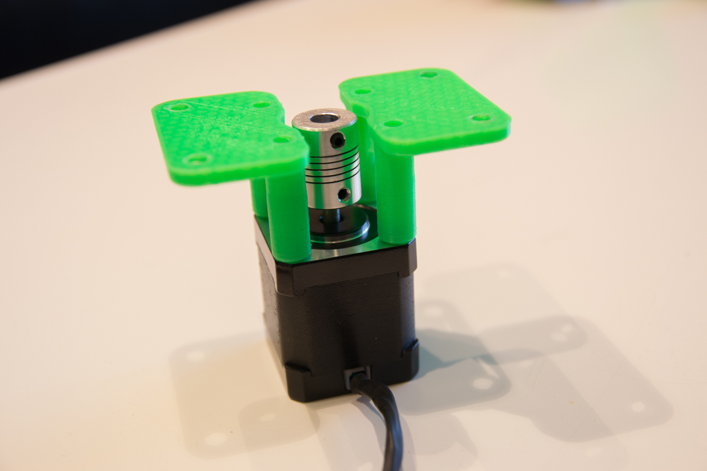
And screw it all together.
You can also tighten the nuts of the X / Z block , it is a bit long to adjust everything as well as possible, take the time to do it well.
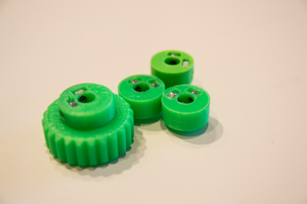
Take the different knobs and blockers and insert the m4 nuts with a forceps, if it forces too much, heat the nuts with a soldering iron or the cooking plate of the kitchen. Then pre-tighten the grub screws M4
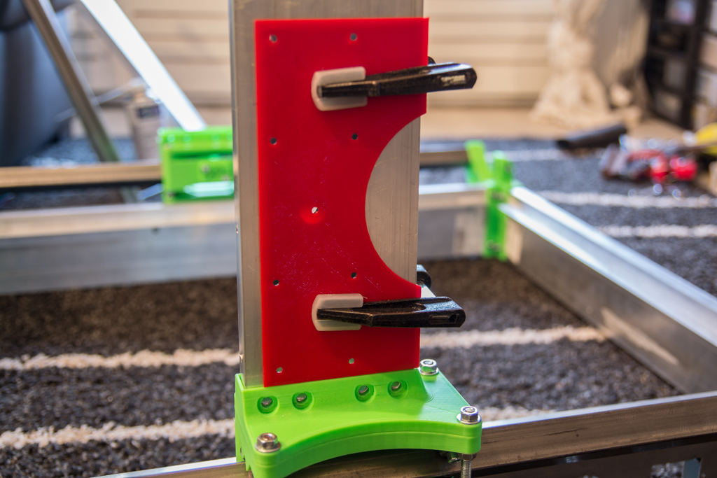
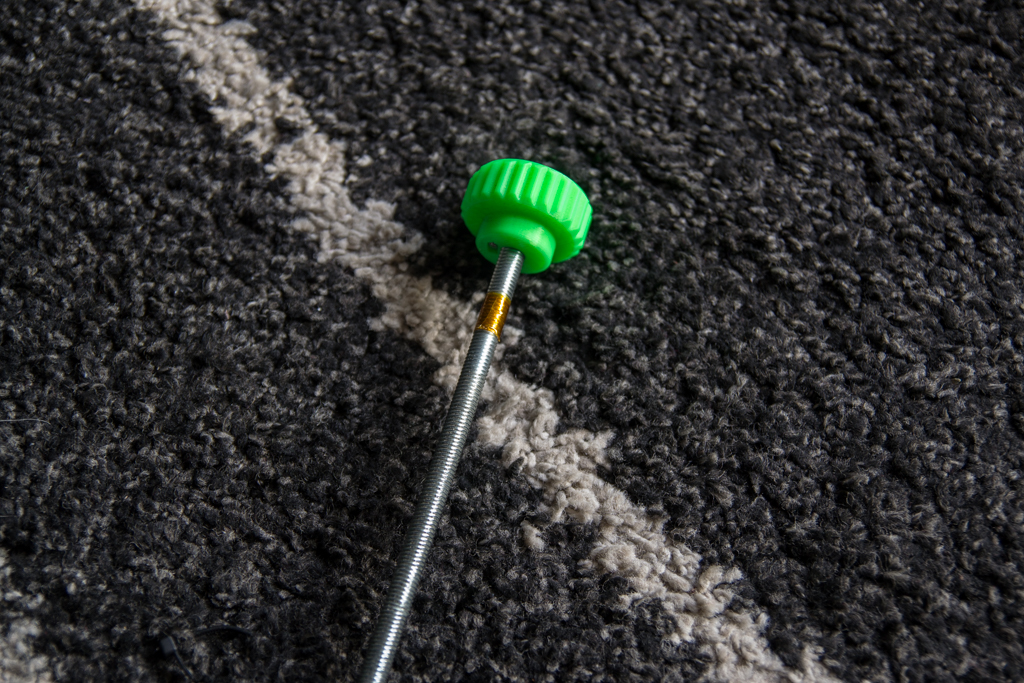
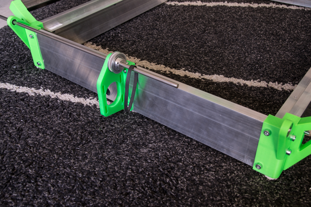
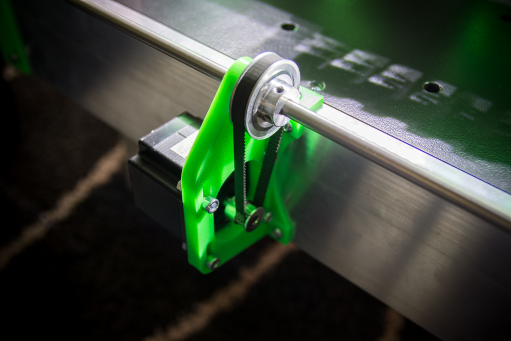
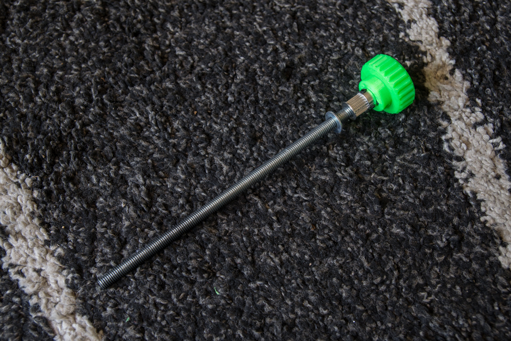
Take the 768mm M8 rod and insert and lock a knob at the end. The visible tape is to limit the game in the bearing and to avoid that you hear “clac clac” when the axis turns fast.
Insert the threaded rod without forgetting to pass the side blockers
First screw the rod into the motor coupler and then the blockers are stopped on each side and tightened, when turning the handwheel by hand, it must rotate very easily.
We go to the back,
Take the Y-motor part, insert a 608zz bearing there, present there to 300mm from the right corner, transfer the holes, point, drill to 3mm and screw there with 4.2mm sheet metal screws
Then pass the 8x688mm smooth rod by threading a small washer of 8 the pulleys 60 teeth and the closed belt of 232mm.
Put the 20 teeth pulleys at the ends, do not tighten anything at this stage. You notice the hole to pass the motor cables.
And install the belts, which must be tight!
- Put one end of the belt in the blocker
- Passing the belt
- Put the other end in front of the blocker to get the correct length
- Without letting go of your mark, remove the 20 teeth pulley, fix the belt in the blocker
- Replace the 20 teeth pulley with the belt on its shaft
- Do the same on the other side
The nema 23 and its pulley 20dents are mounted with screws M5
To adjust the X and Y perpendicularity, nothing is simpler, put both sides of the portal in abutment, and tighten the pulleys 20 teeth, that is, it is impossible to lose the perpendicularity from now on!
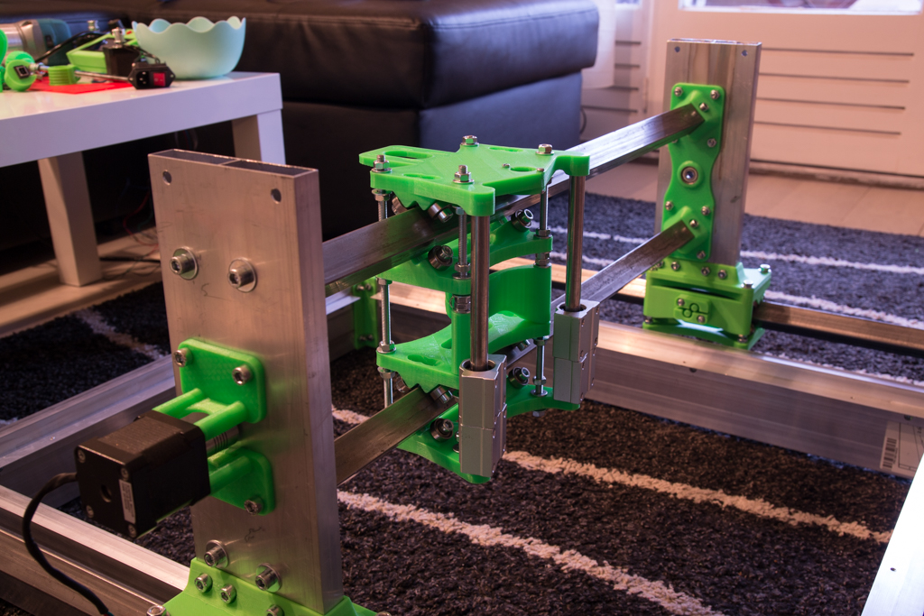
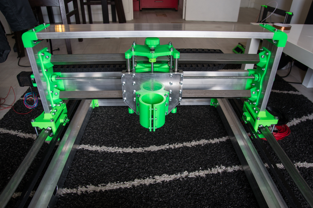
Back to our X / Z block
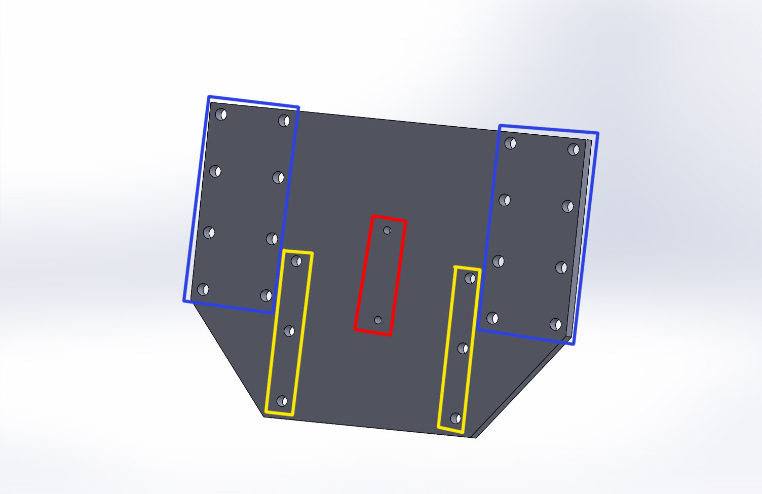
Take the template for the Z plate and fix it on an aluminum or 8mm steel plate
Report contour and holes
For drilling first make a 3mm hole, then:
- The blue parts drilling at 5.5mm
- The yellow parts drilling to 5mm then tapping M6
- The red part drilling to 3.5mm then tapping M4
Screw the Z-nut to the back of the plate with its M8 coupler in
And the spindle holder to the front
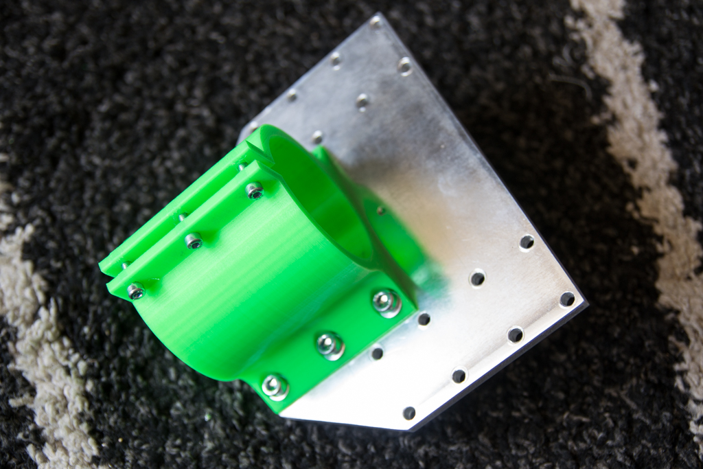
And screw it all to the linear bearings with 16 M5 screws
Take the threaded rod M8x222 and insert a small washer of 8, a pulley 20 teeth, a wheel, and screw it all.
We put on the whole without forgetting to put the Z-blocker

Once all in abutment, we tighten the Z-blocker
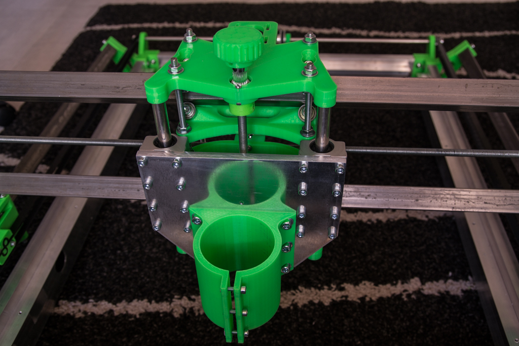
Mount the nema 17 with its 20 teeth pulley and the closed 232mm belt
Take a 702mm box screed, nest the X-corner-left and X-corner-right pieces. Carry out the holes, point at 6mm, reassemble and screw the pieces on the box screed. Put the assembly in position on the machine, in abutment at the bottom. Drill holes, point, drill to 3mm and screw with 4.2mm sheet metal screws
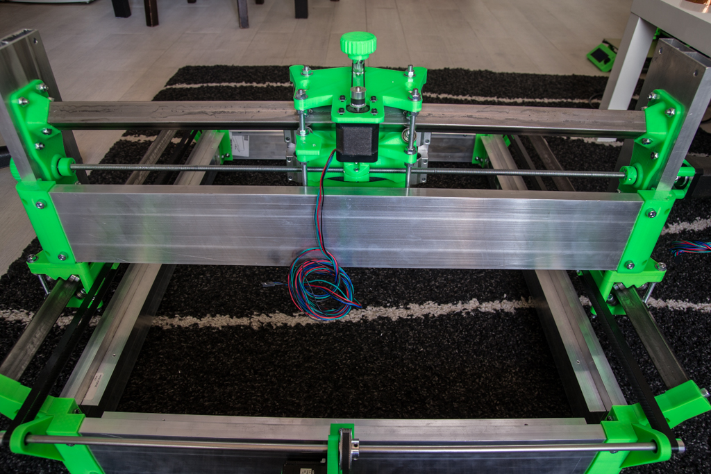
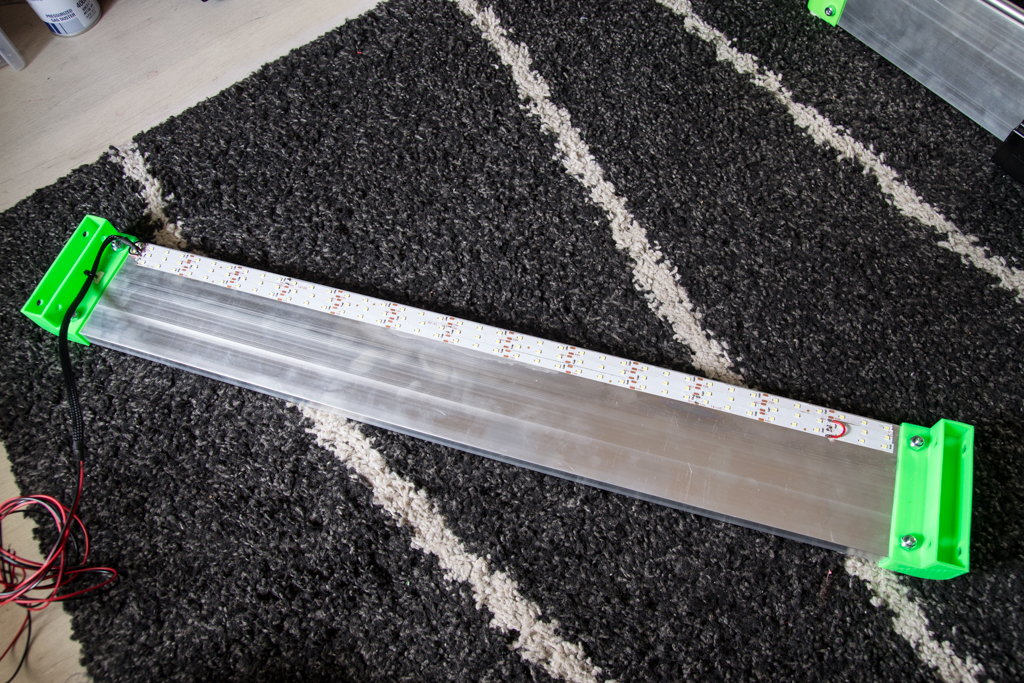
We take the other 702mm box screed, we install the 2 “top-corners” at the ends and then we stick and welds the Led ribbon
And we mount the whole
Dragchains mountage
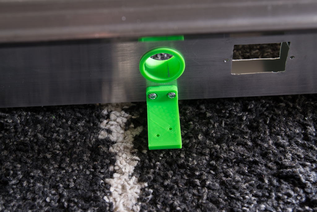
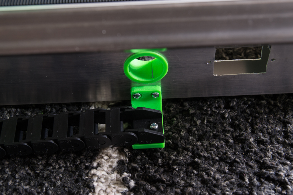
Underneath the left carriage, put the chain in place like this, transfer the two holes with pencil and then drill to 2.5mm and fix the chain with two 3.5mm sheet metal screws
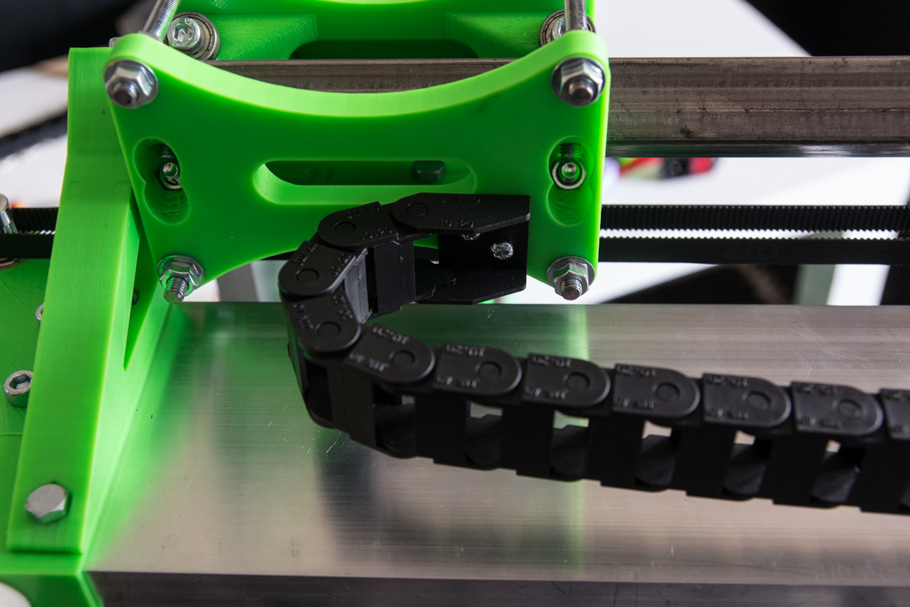
For the end of the same chain, take the Y-chain piece and screw there just under the hole pass cables with two screws of sheet of 4.2mm
For the right length of chain, when you put the gantry back, the chain must make a small loop without touching the bracket.
And the chain is fixed with two 3.5mm sheet metal screws
I have not taken pictures of the details for the top chain, but the fixing holes are already in 3D printing so there should be no hesitation for the editing!
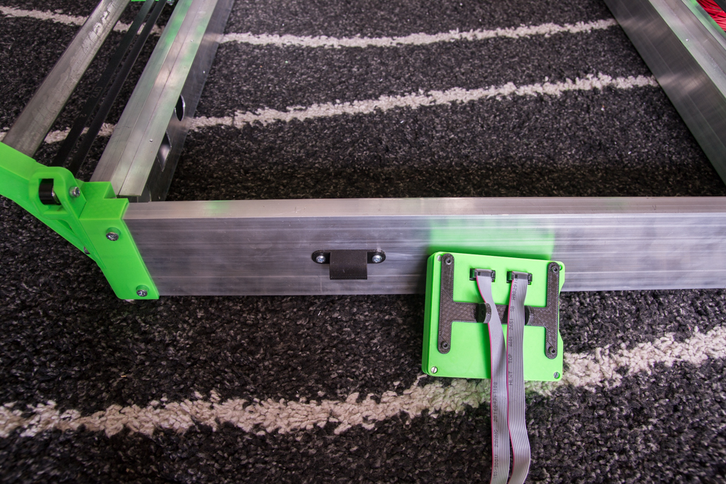
Pass all the cables through the dragchains, lengthen them before if necessary
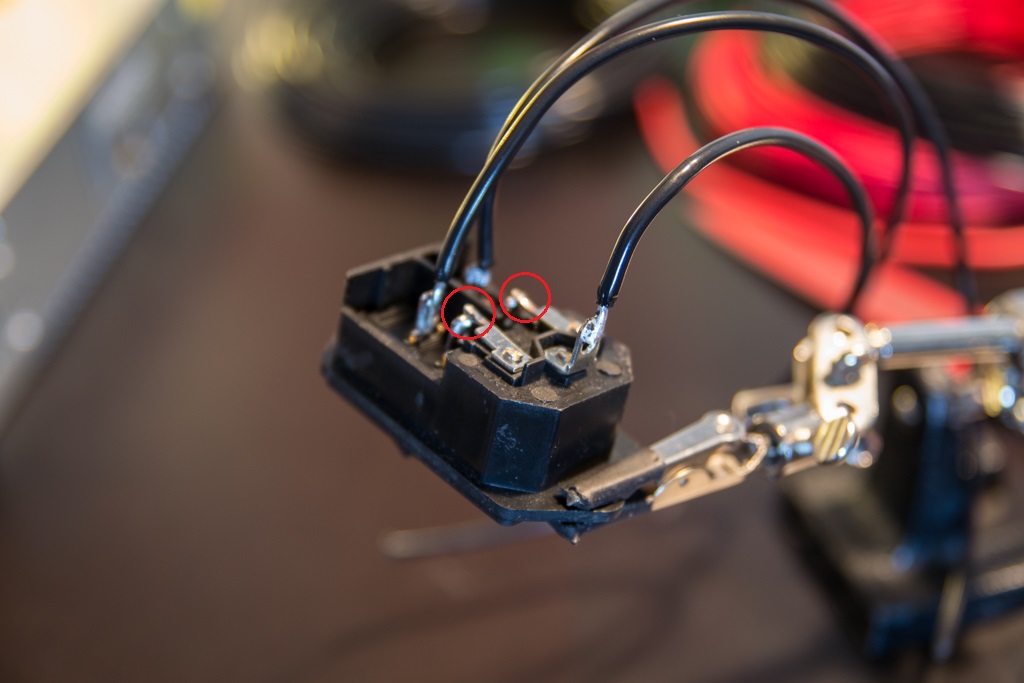
Weld the wires to the plug / switch, don’t forget to weld the metal parts surrounded in red and put thermo sheath on the welds
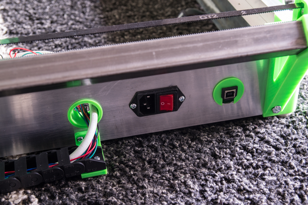
Put it all in place with two 3.5mm sheet metal screws, as well as the USB port, the female USB socket was recovered in an old paper printer and soldered to a male USB plug recovered on an old USB cord
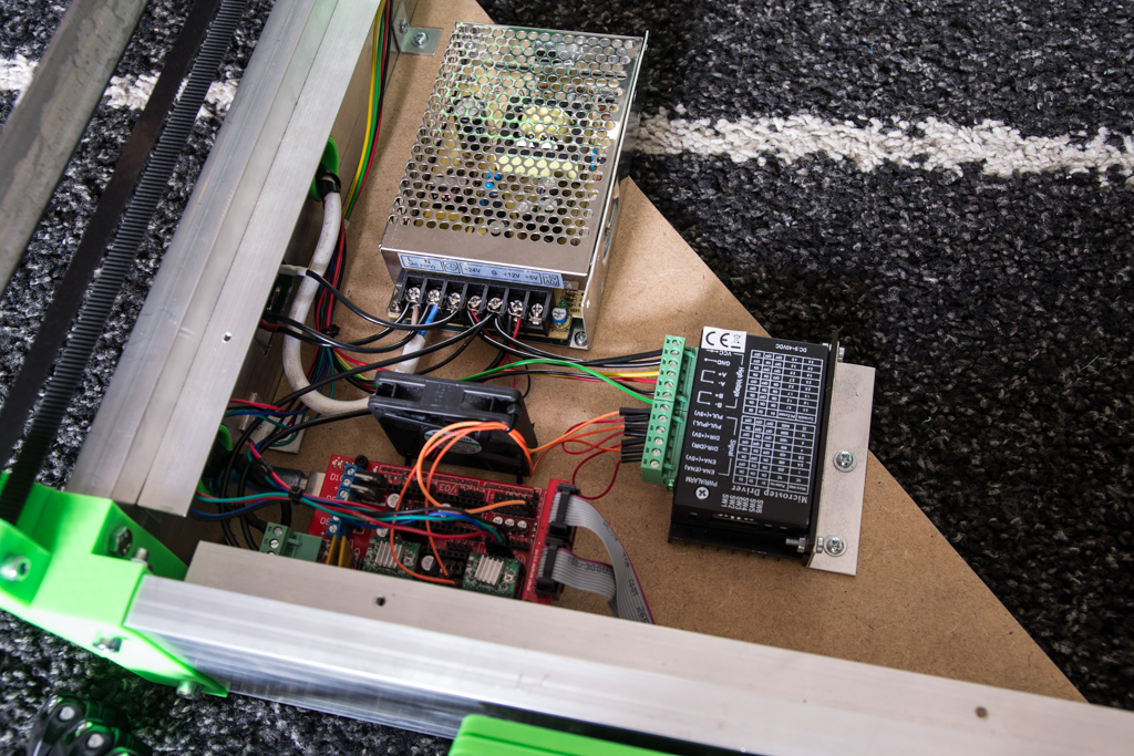
Example of support for the electronics (but make to your taste):
LCD mount
Screw one part of the bracket to the back of the LCD housing and the other part to the CNC frame with two 3.5mm sheet metal screws
And mount it with two 4.2mm sheet metal screws

Voilà, It starts to look like something! .. but missing a trick not?
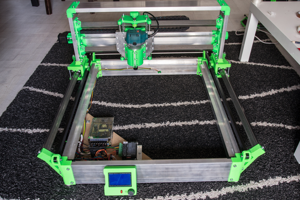
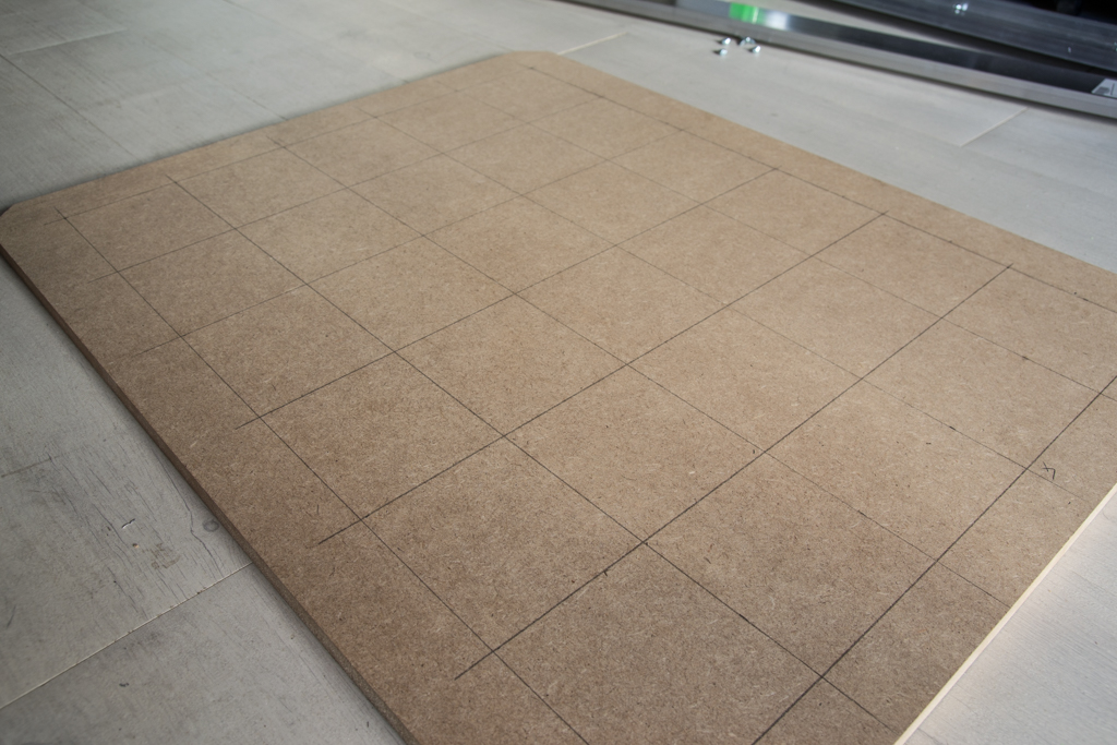
Plate mount
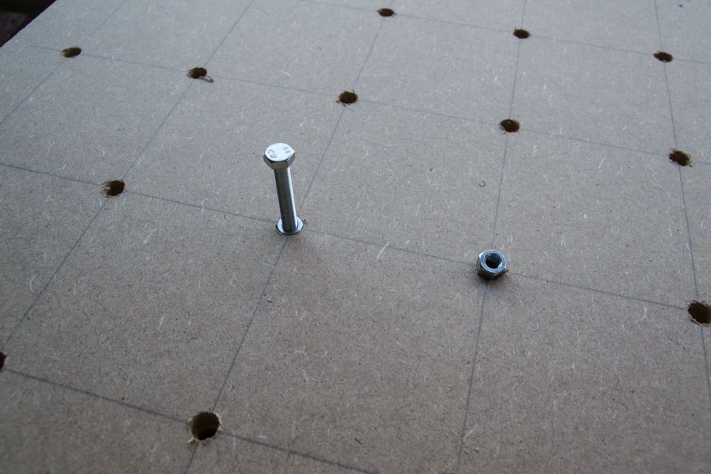
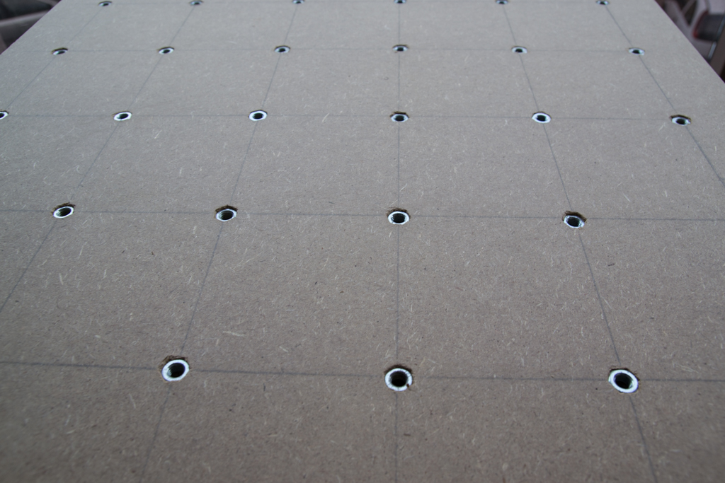
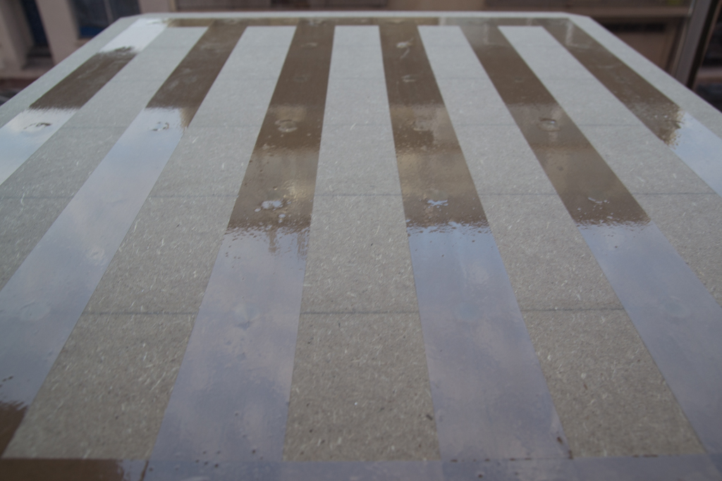
Take a 18mm MDF plate cut to 754x604mm and draw a grid for the fixing screws of the pieces, drill all at 9mm, then only on 8mm of depth, drill at 12.5mm
Then take M8 nuts which are put on the end of a long screw M8 and we hit with the hammer to push it, your neighbors will adore you: p
Then cover with large tape so that the dust does not arrive at the electronics
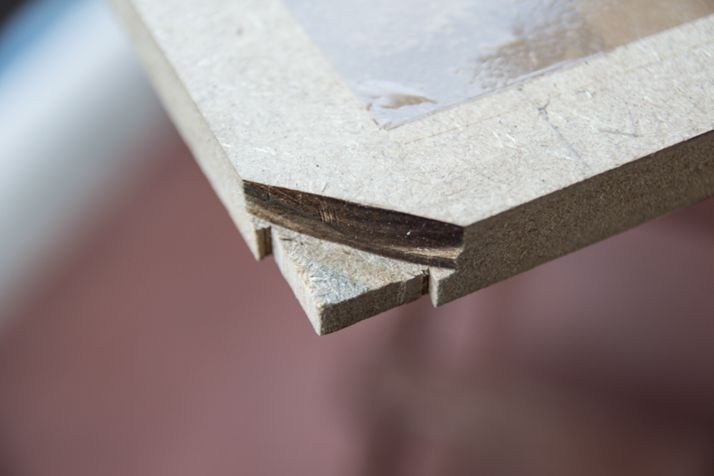
Then cut corners like this so that it fits the shape of the plastic part

And cut like this because of the height of the screws underneath
And you can screw reinforcements underneath
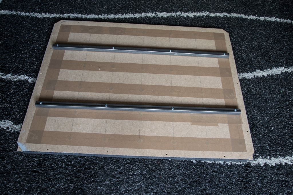
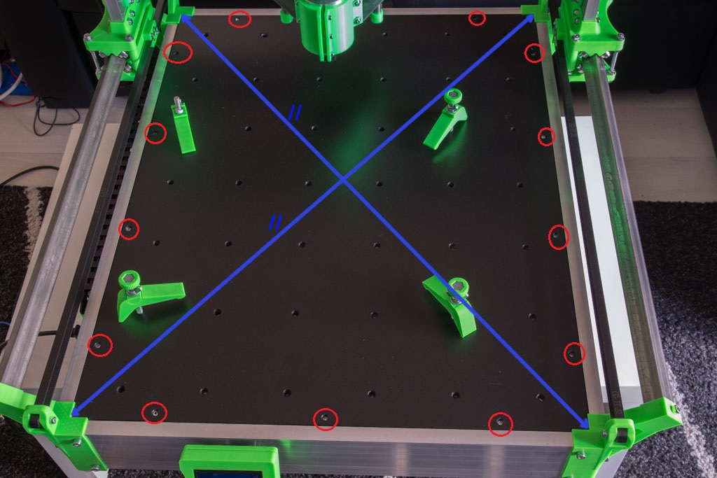
Put your tray in place
- Measure diagonals of the frame (blue)
- Drill holes diameter 3mm to 10mm from the edge through the wood and the angle bracket that supports the tray (in red)
- Remove the tray
- Drill all holes in the tray to 4.5mm
- And drill to 8mm diameter only on 5mm max depth! (For the screws heads)
You can paint the tray and screw it on using sheet metal screws 4.2×25, but hey, we have not done the wiring !
Sublime de chez sublime, ha si je peux en faire une ,je pourrais enfin créer ce que j’ai en tête est retrouver le bonheur merci de donner de l’espoir a des personne commme moi, merci
Bonjour Romain,
Penses tu qu’il soit envisageable de doubler l’axe y sans trop de difficultés, afin de pouvoir placer des plaques complètes de Depron?
Mécaniquement, seules les longueurs des règles et carrés 25×25 de l’axe y changent….
Une modification du marlin permettrait elle cette manip?
Merci
Pas besoin de changer la config Marlin pour un changement de dimensions, par contre, doubler la longueur des tubes carrés va engendrer un manque de rigidité de manière exponentielle !
Très beau !
Y’a juste un truc que je n’ai pas compris (du tout) :
“Le scotch visible est pour limiter le jeu dans le roulement et éviter qu’on entende des « clac clac » quand l’axe tourne vite.”
Bonjour, la tige filetée a un diamètre légèrement inférieur (un dixième) au diamètre intérieur du 608zz, du coup je comble ce jeu avec un tour de scotch sur la tige filetée.
Bonjour Romain
Sur l’axe Z les tiges de D12 ont une longueur de 192mm, or la longueur disponible est de 199mm. Il faut bien sûr du jeu mais as-tu une raison pour avoir mis cette côte ?
Bonjour, oui, il faut un peu de jeu pour le réglage de la pression des roulements sur les tubes carrés, mais ne t’inquiètes pas, ça ne bouge pas car les tiges sont montées en légère force sur leur support imprimé 😉
Bonjour
J ai quasi fini le montage mais je me pose une question sur les tenseurs de courroie je n arrive pas tendre ma courroie elle glisse dans le tenseur.
Je pense que je l utilise mal
Avez vous un conseil pour mettre la courroie
Bonjour, oui pour l’instant la tension des courroies n’est pas pratique, une mise à jour est prévue pour début octobre avec des tendeurs de courroies dignes de ce nom !
En attendant la méthode la plus efficace consiste à présenter la courroie devant son logement, puis d’enlever la poulie de son axe, fixer la courroie, remettre la poulie en force sur son axe.
Super, j ai commencé a en faire une , cela est un peu compliqué pour l’impression 3 D car je le fait avec fil très solide et il me faut 2 fois plus de temps en impression mais cela sort superbe. Pas de retouche a faire.
Je fait faire toute les pièces a mon imprimante, je vous dirais ou en est le montage dans 15 jours.
Super ! n’hésites pas à t’inscrire sur le forum pour présenter ta machine
Bonjour,
je suis en train de fabriqué votre machine, mais une question me ronge,
On peut faire du 550×550 pour les X et Y mais combien au niveau de l’axe Z?
Merci d’avance.
Bonjour, Z a un débattement de 80mm
I can’t register in the forum (do you check new user requests? :)), so will ask here:
I have made X/Y frame and started making vertical frame (only the screeds are connected now). But now there is a problem, that when it rolls, it looks like rails are not exactly parallel, because when you push the caret to the front or to the back or the X/Y frame only one side of it touches the frame, the other is about 2mm away.
Is it very bad or will it work normally with such inaccuracy? Do you have any thoughts how that can be fixed?
Hi !
Your forum account is activated.
your difference of 2mm is normal, when you’ll put the two Y belts, you’ll put in abutment the two sides and you tighten the pulleys and everything will be square 😉
Hi i have a question about the MDF Plate, I checked all the stores near me and also online but I can’t find any 18mm plates. I only find 16mm or 19mm, would it be better to take the ticker or thinner plate?
Hello,
19mm will fit without problem !