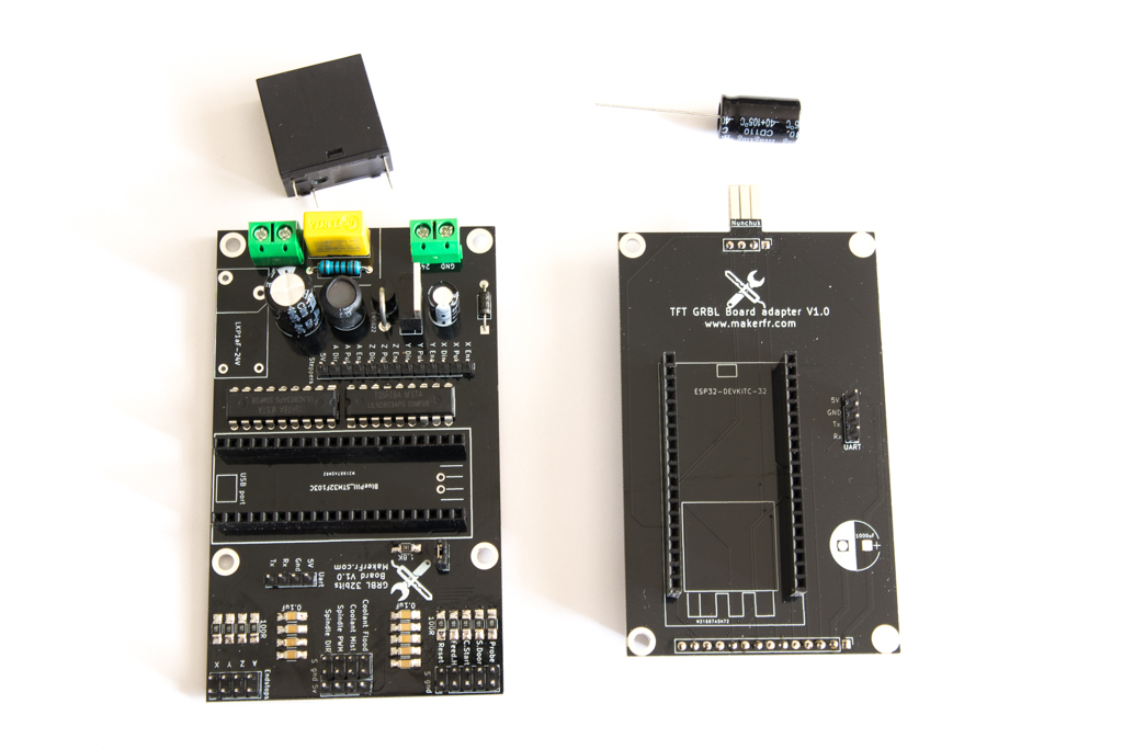
Assembly of different parts of the kit
When you received your GRBL 32 bits board kit, there was a component to solder by yourself on each board, the soldering relay on the GRBL board, and a capacitor on the TFT board, but also a chunk of 4 pins header to be solder on the TFT itself.
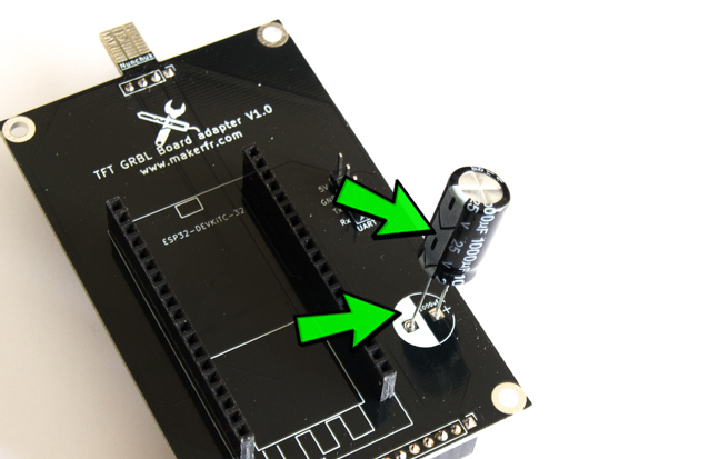
Solder the capacitor on the board provided for the TFT, be careful to put the white band of the capacitor on the side of the white mark on the PCB !!! (spotted with green arrows on the photo)
Solder the relay on the GRBL card, we can not go wrong because the contacts are asymmetrical.

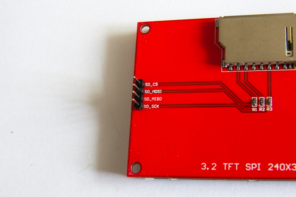
Solder the 4-pin header on the TFT, on the opposite side of the screen
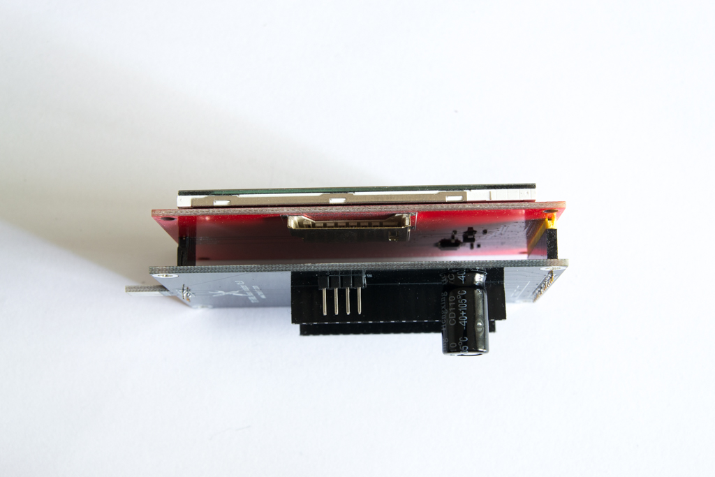
We put the TFT on its board
Then the STM32 and ESP32 modules, look at the drawing on the board to make sure you don’t make wrong sense, at risk of burning your modules!
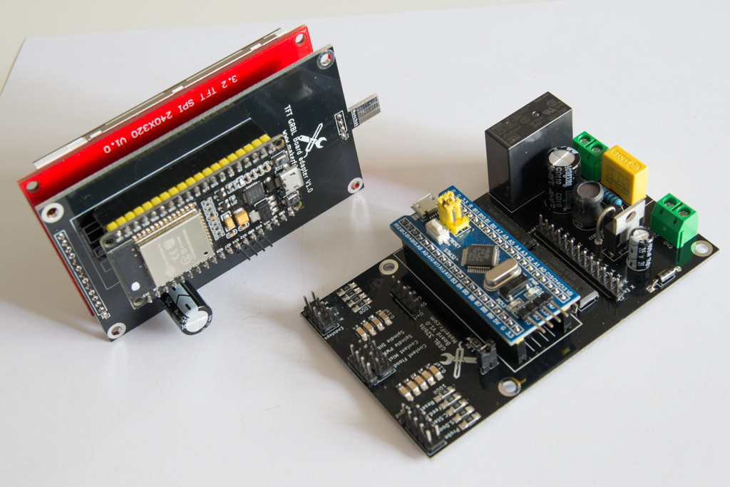
It’s assembled !
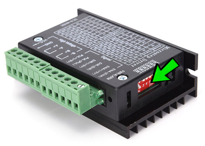
TB6600 drivers setting
If you mount a RS-CNC32, set the TB6600 drivers in 1/4 step
If you have 2.8A motors, that will give from SW1 to SW6: ON.OFF.OFF.OFF.OFF.ON, otherwise, refer to the table on the TB6600
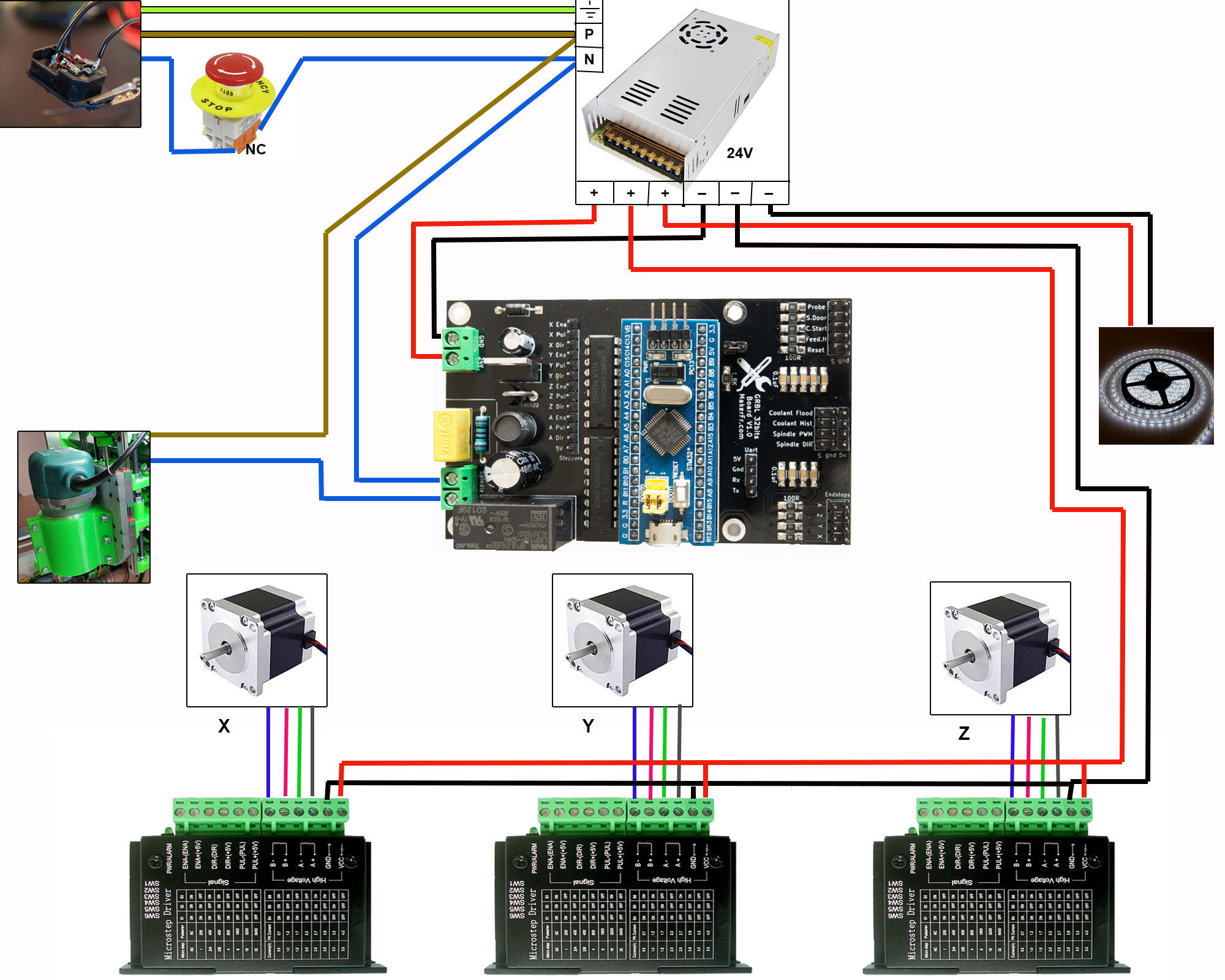
Wiring diagram
Power diagram
The color of the stepper motor cables may vary from one manufacturer to another, refer to the manual that came with your motors.
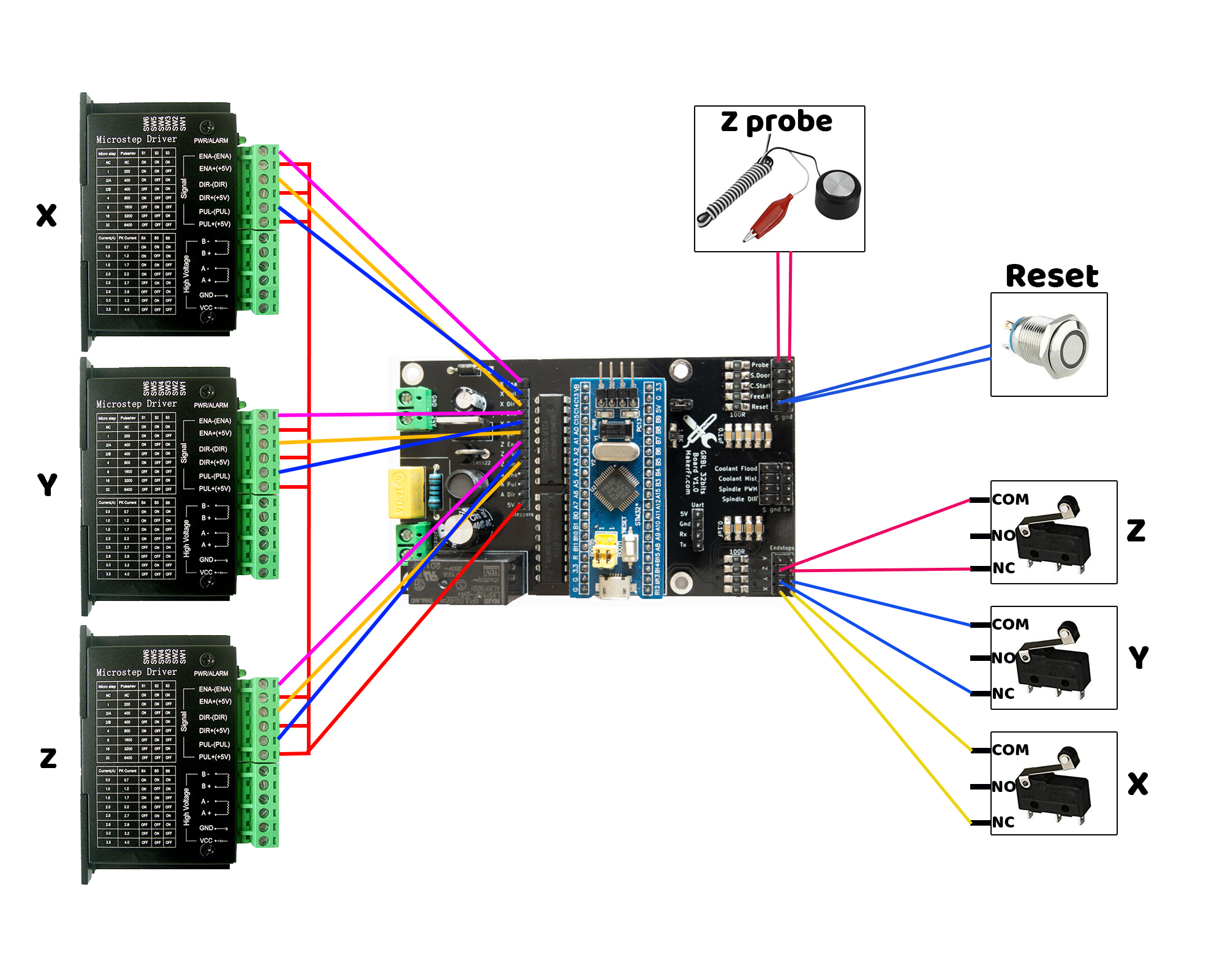
Command Diagram
Z probe and reset button are optional
It is also possible to control a spindle or a laser with the Spindle PWM pin!
Think to use shielded cables for the switches
Attention, it is imperative to wire the endstops or put jumpers in place before the first test, otherwise the machine will believe that the endstops are triggered and will get directly an alarm.
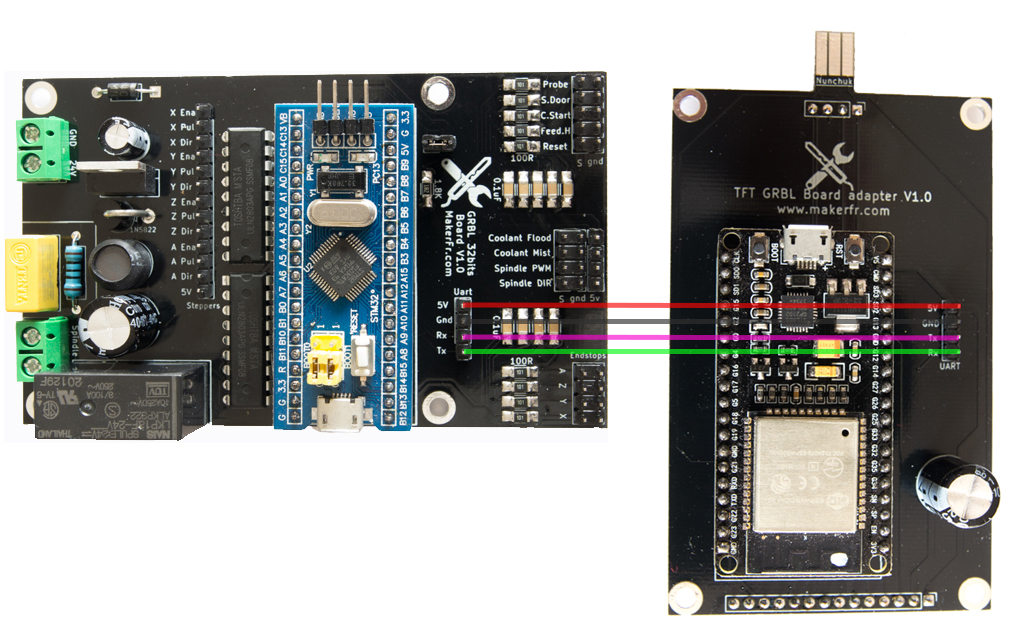
Connection diagram between GRBL board and TFT board
Yes TX goes on RX and vice versa!
You can also use shielded cable (at least for both RX and TX wires)
All is wired ! Next step:
GRBL Firmware for STM32, easy way
or
GRBL firmware GRBL for STM32, custom way