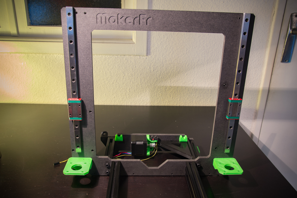
Frame assembly
After having cut the V-slot aluminum profile to the correct length with a perfectly perpendicular cut, tap at M5 all the holes at the ends of the profiles (16 holes in all). Attention, Vslots profiles of some suppliers tapped M6 and suddenly it will be necessary to use M6x20 screws and enlarge the holes of the frame to 6mm.
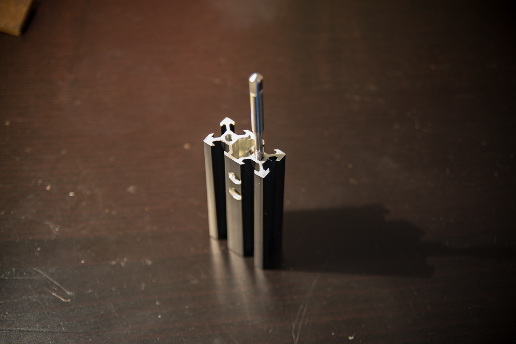
And drill two 8mm holes as in the picture on the two profiles. It’s just to pass the cables through the profiles.
Hand tighten, without tightening, the aluminum profiles to the frame.
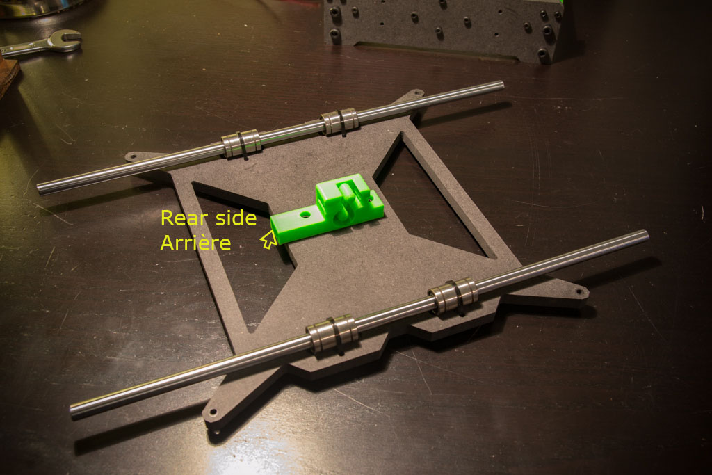
At the back of the frame, push the M3 nuts into their 8 slots
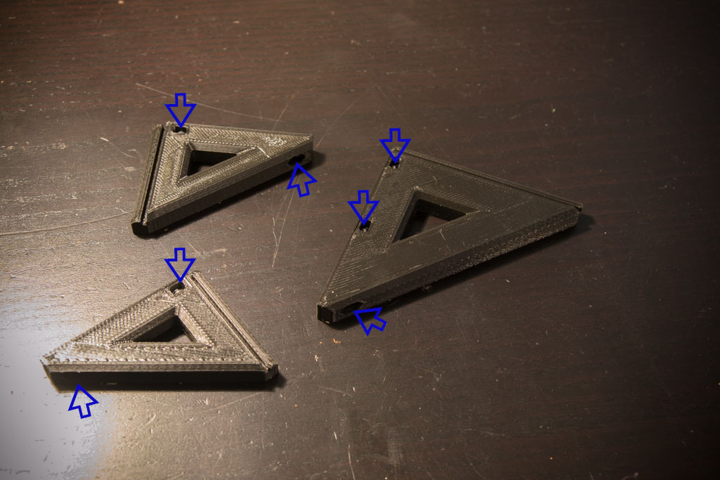
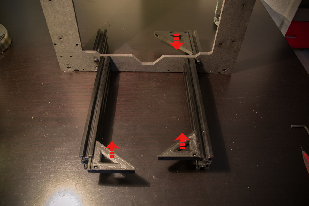
Insert M3 nuts into the Y reinforcements slots
And slide them into the V-slot rails (top groove)
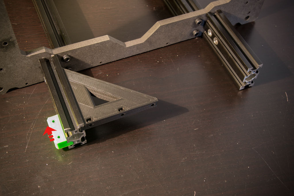
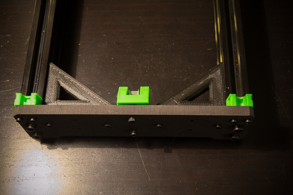
Insert into the Vslot rail the green piece (bottom groove)
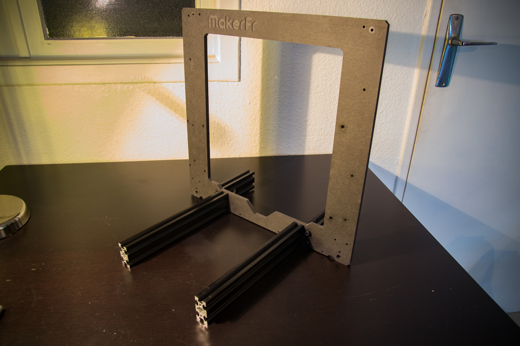
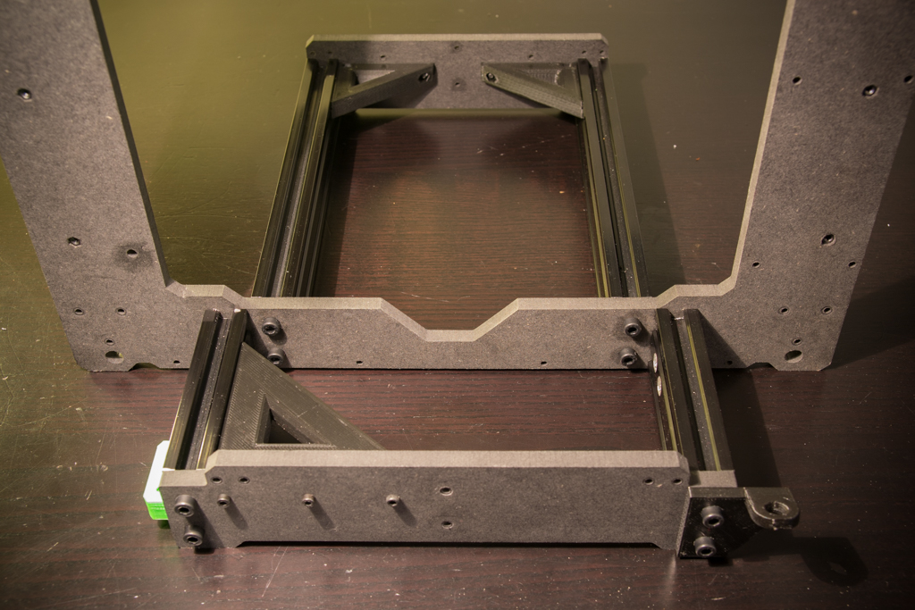
With the M5x20 screws screw the corresponding frame parts to the front and back, do not forget the Z reinforcement at the right rear as in the picture.
Once all parts of the frame are assembled, make sure you are on a flat surface and tighten all M5 screws, the 6 feet of the frame should be on the ground.
then screw the Y reinforcements with M3x16 screws
Insert M3 nuts into all the slots of these parts (to insert the nuts into the rectangular slots, help yourself with the needle nose pliers)
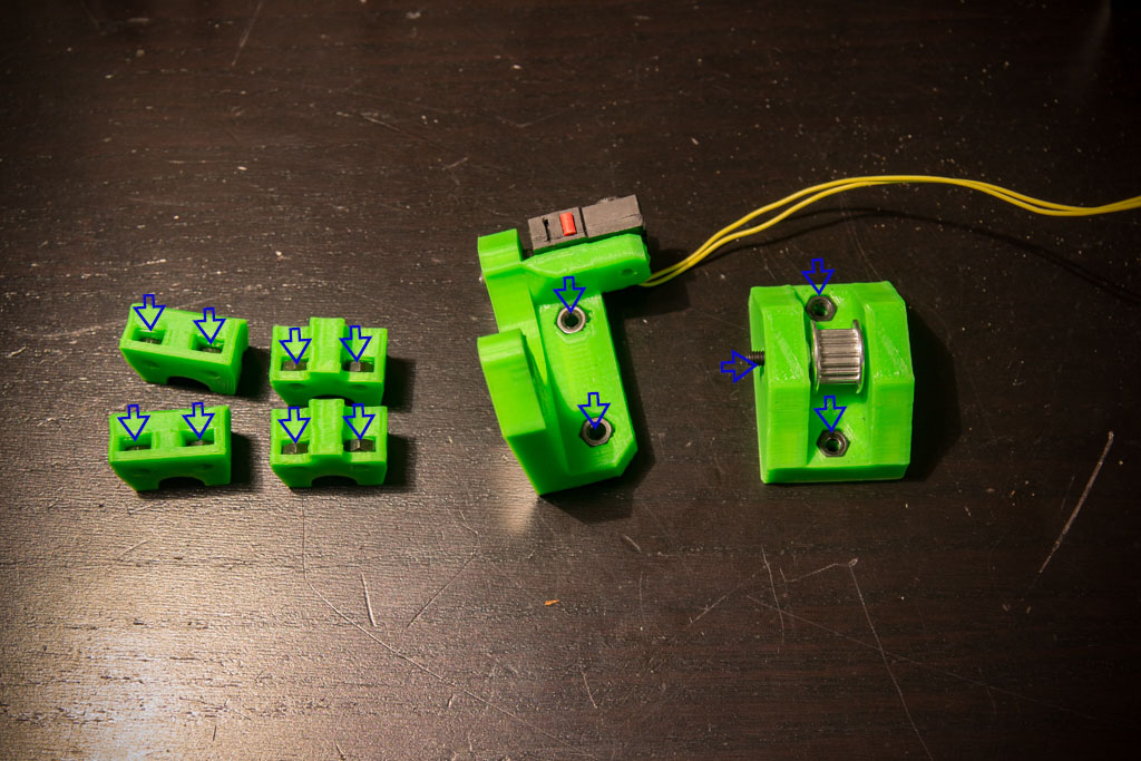
Screw the pulley with the M3x25 screws and screw the switch with two M2x10 screws (wired on the NO and C terminals, and remove the blade by pulling on it)
Screw the Y pulley module with two M3x20 screws, but do not tighten, instead, leave space between the workpiece and the frame.
Screw and tighten the Y smooth rods support parts at the front and back with M3x12 screws
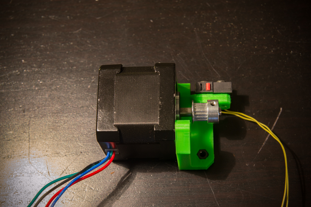
Screw the Y motor to its support and add the 16-tooth pulley and the wired switch to the NO terminals with two M2x10 screws like this:
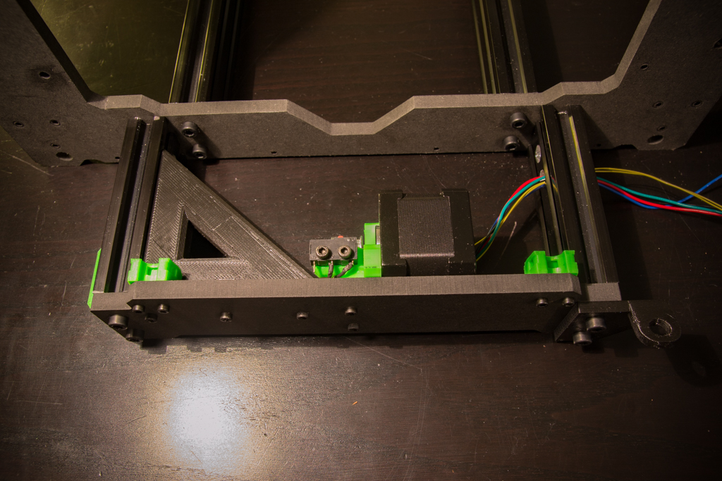
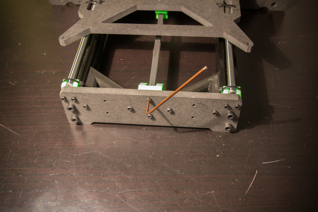
Screw the assembly on the back of the frame
On the front side, screw the” Z bottom” brackets
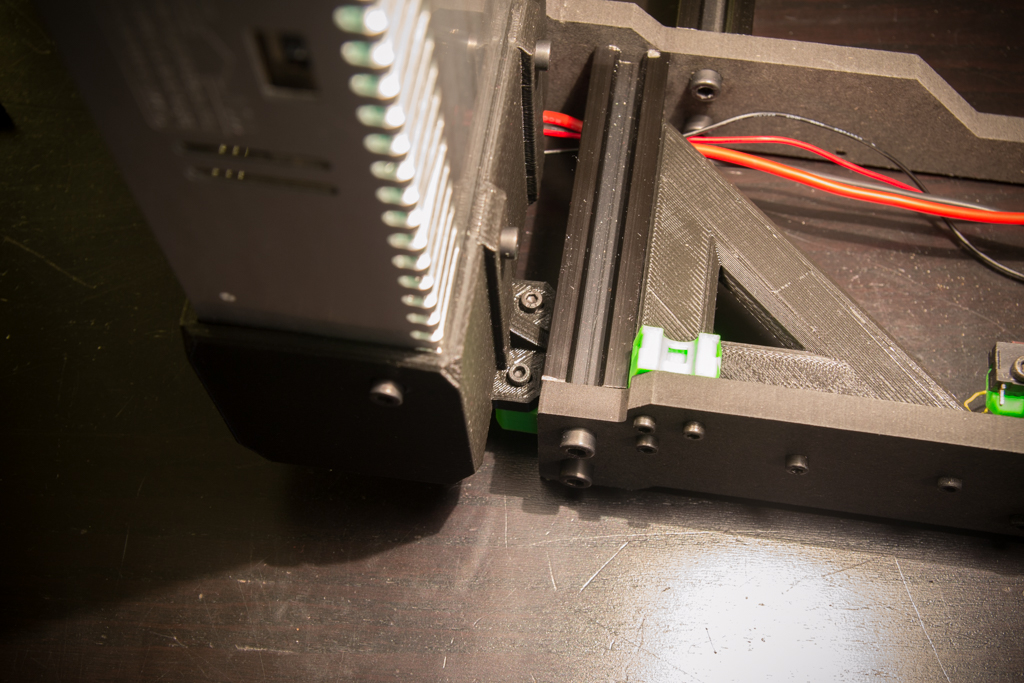
Before fixing the slides MGN12, clean them well with a cloth because they are often delivered sticky, then coat the grooves with fine oil, there should not be a big point nor game. And attach them to the frame without them. tighten for the moment with 8 screws M3x10
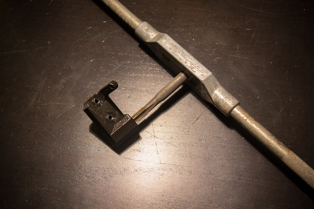
Tape M8 BackCorner
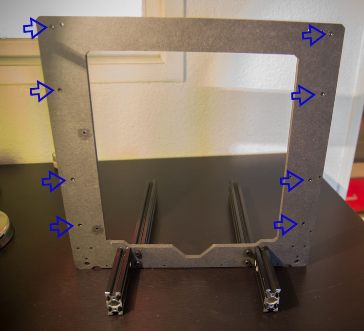
Screw on the M8 threaded rod and insert two M3 nuts marked by the blue arrows.

First we put the threaded rod in the bottom piece, then we screw the top
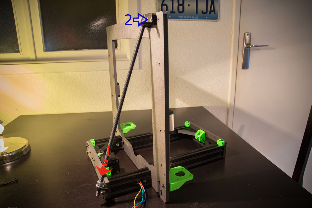
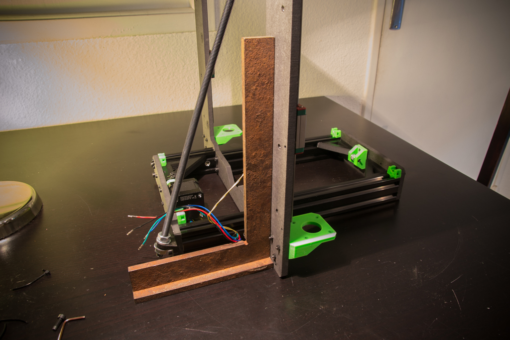
Play on the M8 nuts so that the frame is perpendicular to the ground (always on a flat surface)
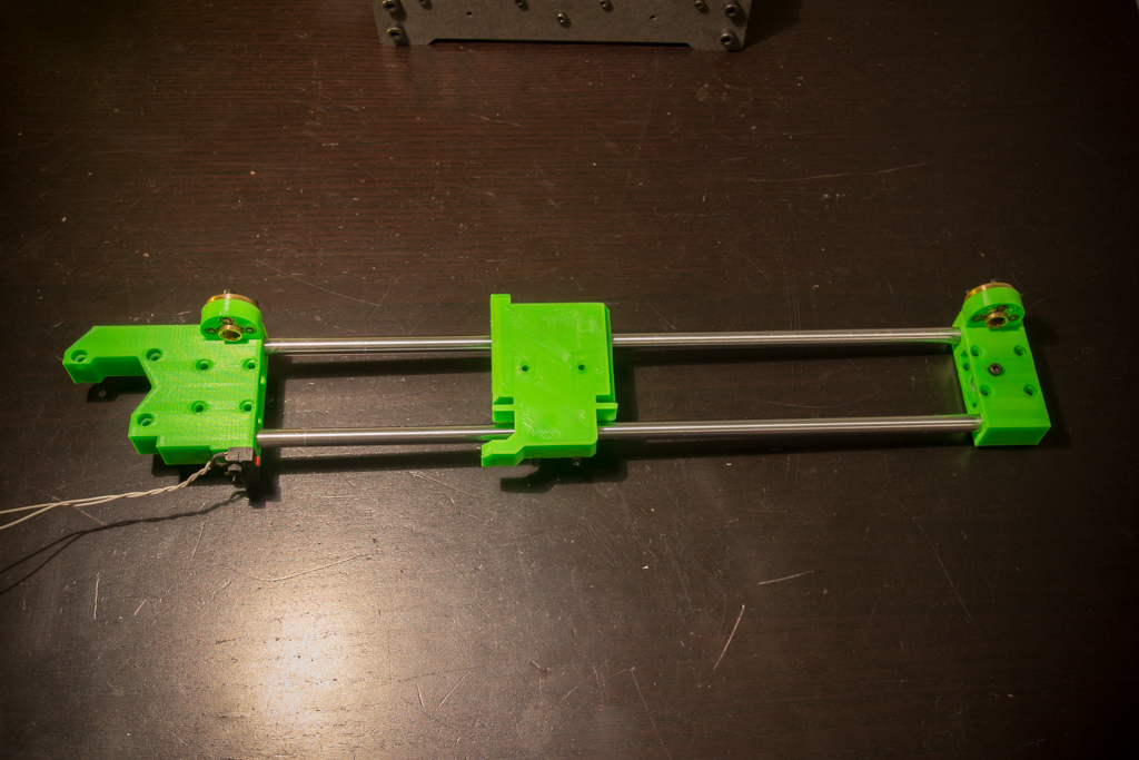
Take heatbed support and zip the 4 LM8UU bearings in the middle of their housing, screw the piece Y_Belt, the long side of this piece goes to the back of the machine.
Clip the assembly pressing the end of the rods and then zip them to their support

Put the Y belt

Tighten the screws of the Y pulley module, check the tension of the belt, it should not be too loose or too tight, if it is not the case, repeat the operation until you have the correct tension.
Power supply assembly
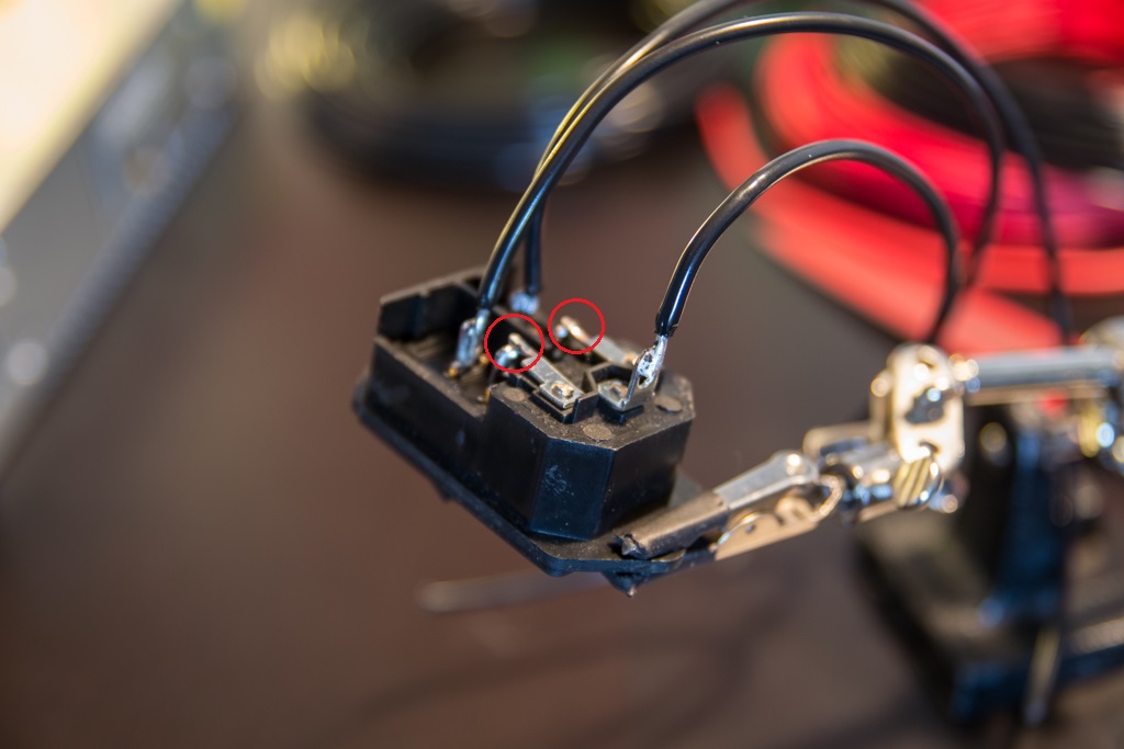
Take the electrical plug and switch module, weld the surrounding parts in red and solder the cables, then put heat shrink at the welds.
Screw the plug module into the plastic holes without nuts with two M3x8 screws
Connect the phase, the neutral and the ground, then a pair of 16AWG cables on the 24V out that will feed the MKS Base and a pair of small section cables that will feed the RGB leds strip.

Screw the base of the power supply with 3 screws M4x8
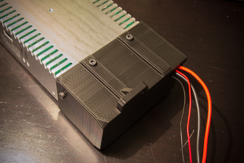
On the front attach the power supply with two M4x12 screws and then on the back with two M3x16 screws
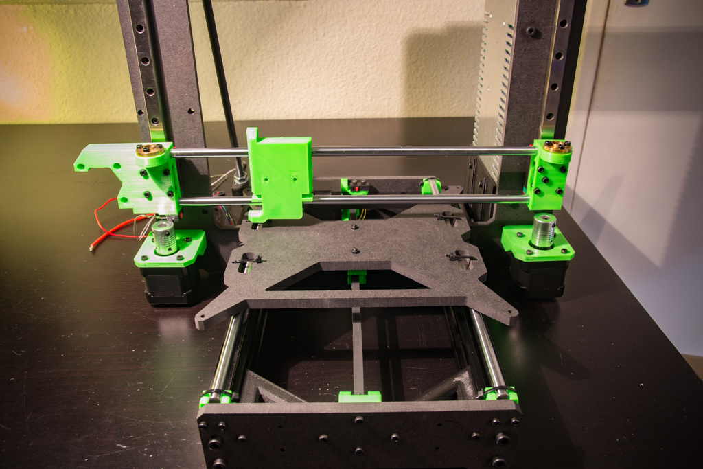
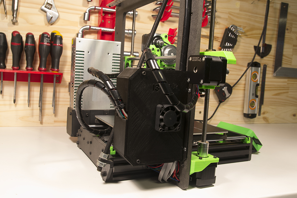
X / Z module assembly
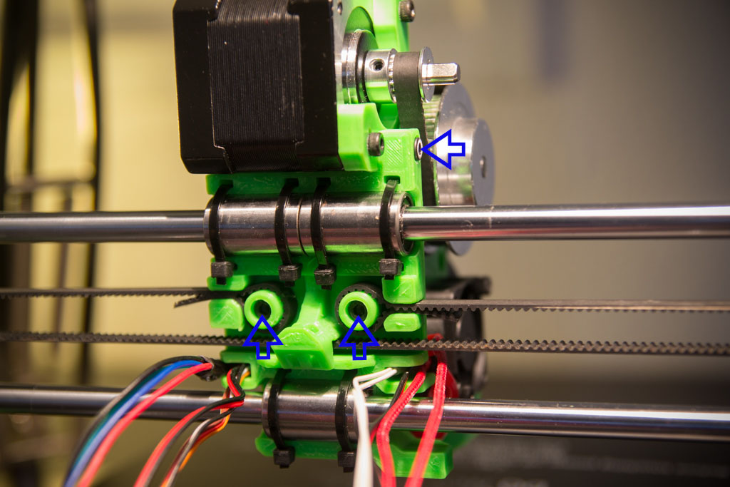
For the Y axis, tighten the copper nuts of the leadscrews with 6 M3x12 screws, the X pulley with a M3x16 screw and a nut, the switch wired to the NO terminals with two M2x10 screws.
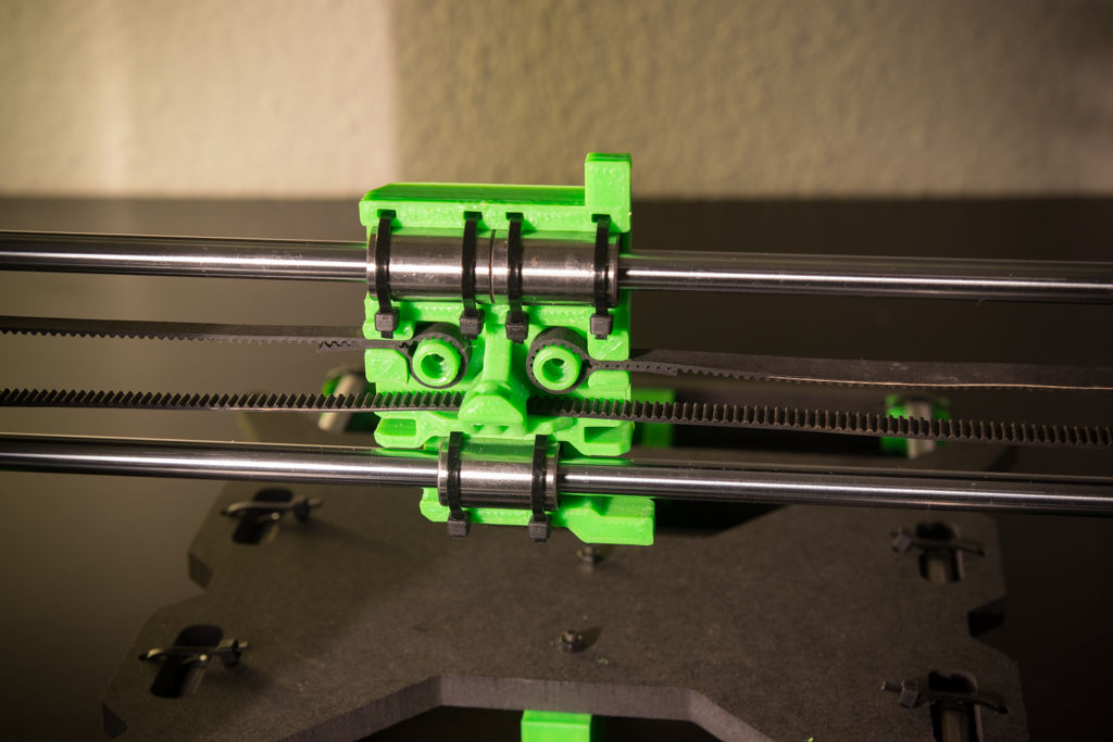
Zip X-dolly on LM8UU bearings, and put a gap of about 306mm between the end pieces.

Put a little threadlock on 8 screws M3x20 and screw all on the slides by tightening moderately.
Check that the Z-assembly slides well, then slide the X-carriage at the top of the Z-axis and tighten the screws at the top of the slides, place the X-carriage at the bottom of the Z-axis and tighten the screws at the bottom of the slides.
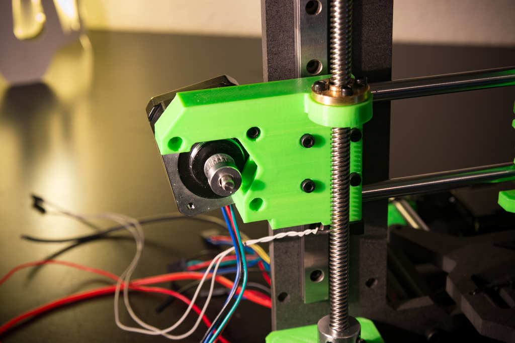
Screw the Z motors with 8 M3x10 screws, and screw the 5mm / 8mm couplers.
Put the leadscrews and tighten them in the couplers
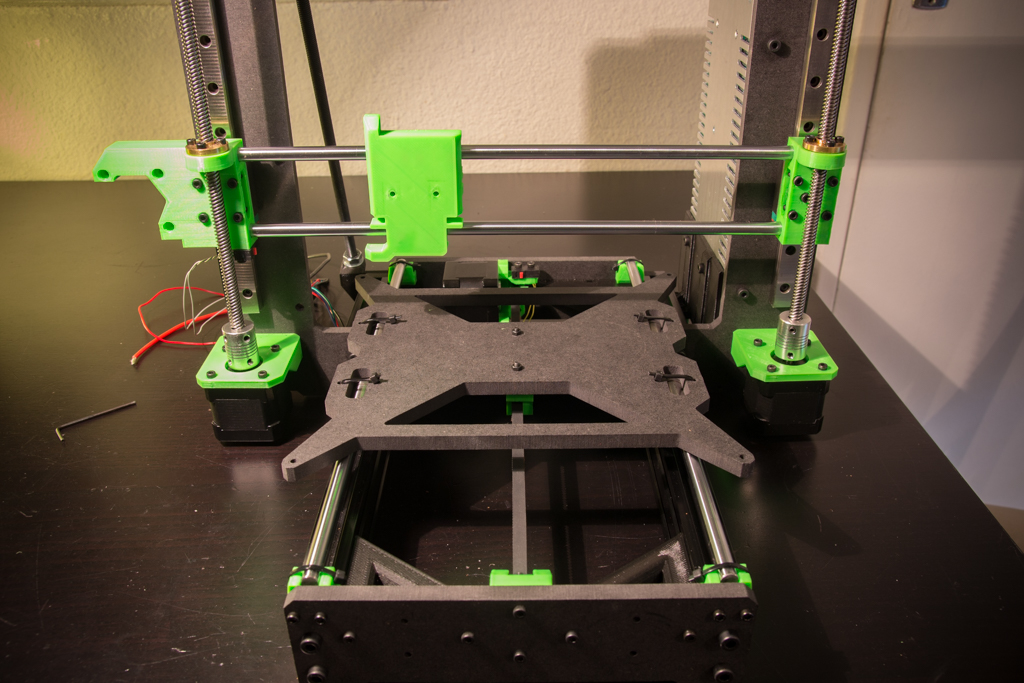
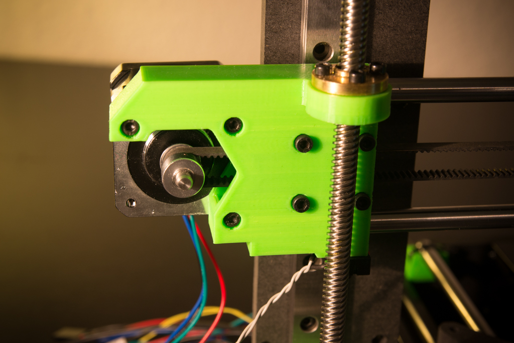
Put the X motor in position with a single M3x16 screw for the moment, as in the pic
Put the X belt
Put the other screws, check the tension of the belt, it should not be too loose or too tight, if it is not the case, repeat the operation until you have the right tension.
Heatbed assembly
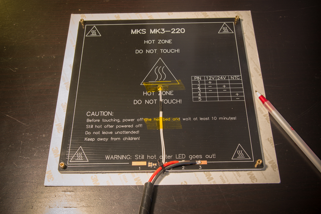
Take your heatbed MKS MK3-220 and screw the 4 standoff 6-32 M3 in the 4 holes of the corners of the board.
Solder a pair of 16AWG cables to the 2 (+) and 3 (-) contacts for a 24V connection.
Glue the probe with kapton tape (heat resistant)

Take a bed liner and trace the outlines with the pen and cut it a little larger than the tray size
Glue the liner on the tray and cut what’s over with a good cutter.
Then fix it to the bed support with 4 screws M3x12
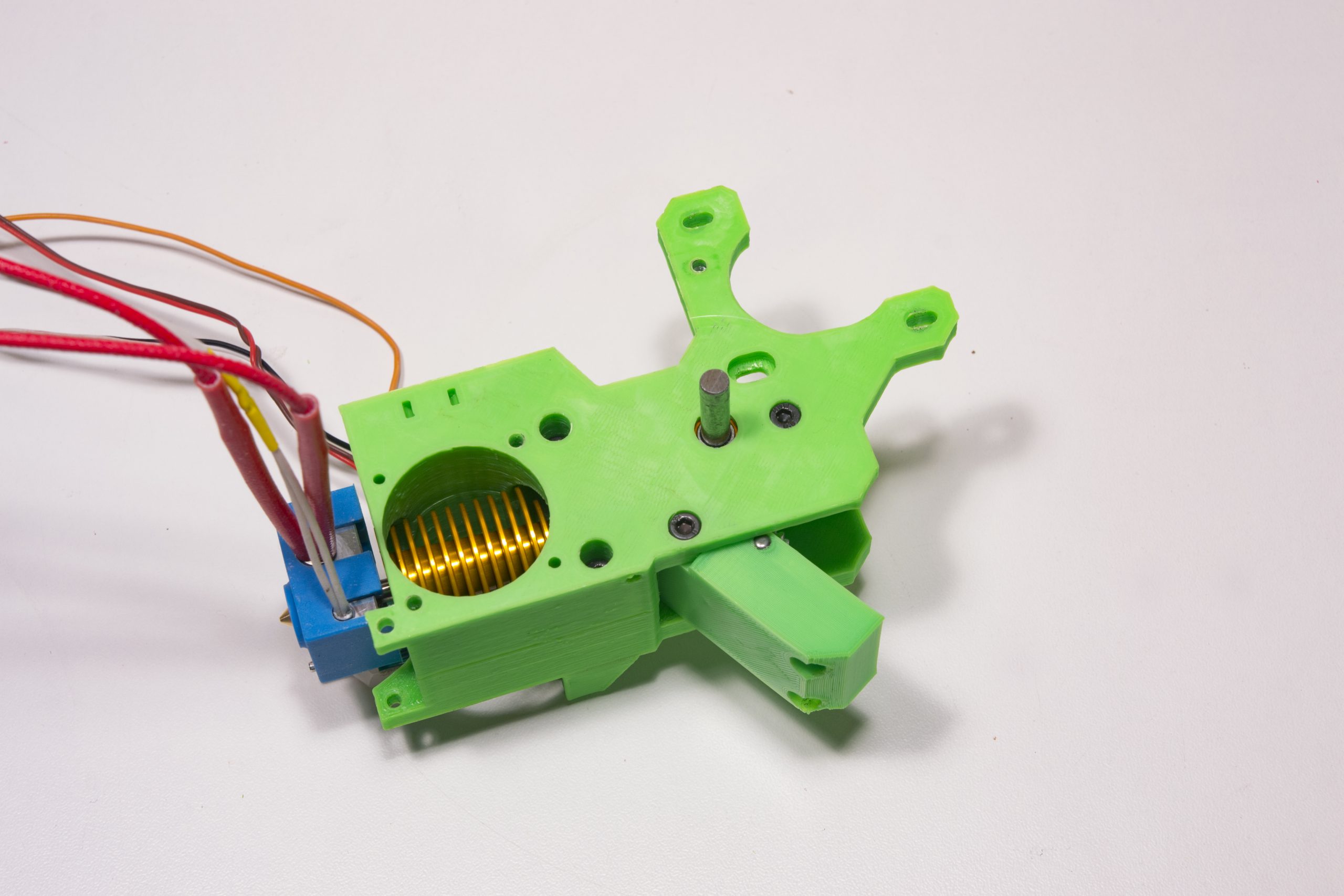
Extruder assembly
We insert M3 nuts in all the locations indicated by blue arrows
The two square nuts supplied with the double gear are inserted at the yellow arrow.
We tap the hole on the side indicated by the purple arrow
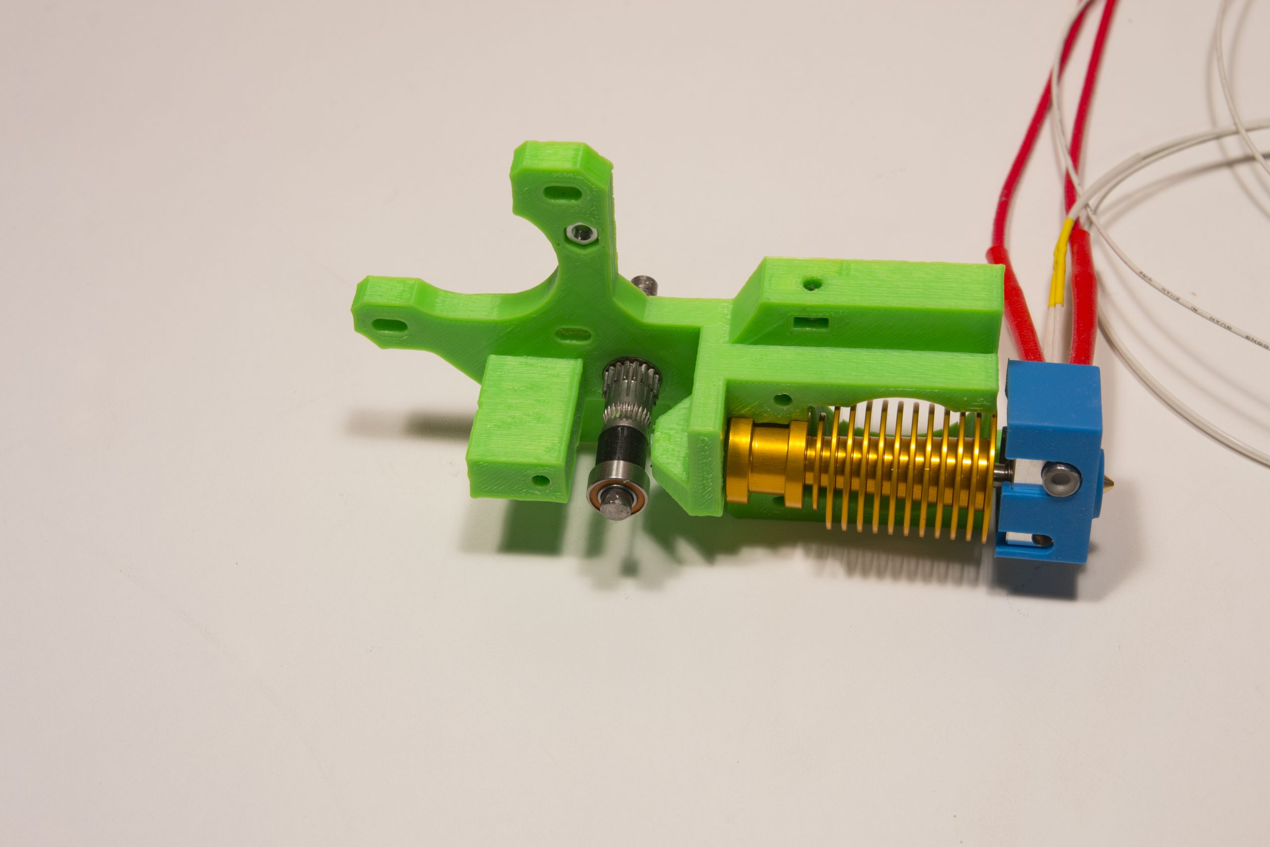
We thread the gear on needle cages in the flap of the extruder and we slide its axis provided with. (Red arrow)
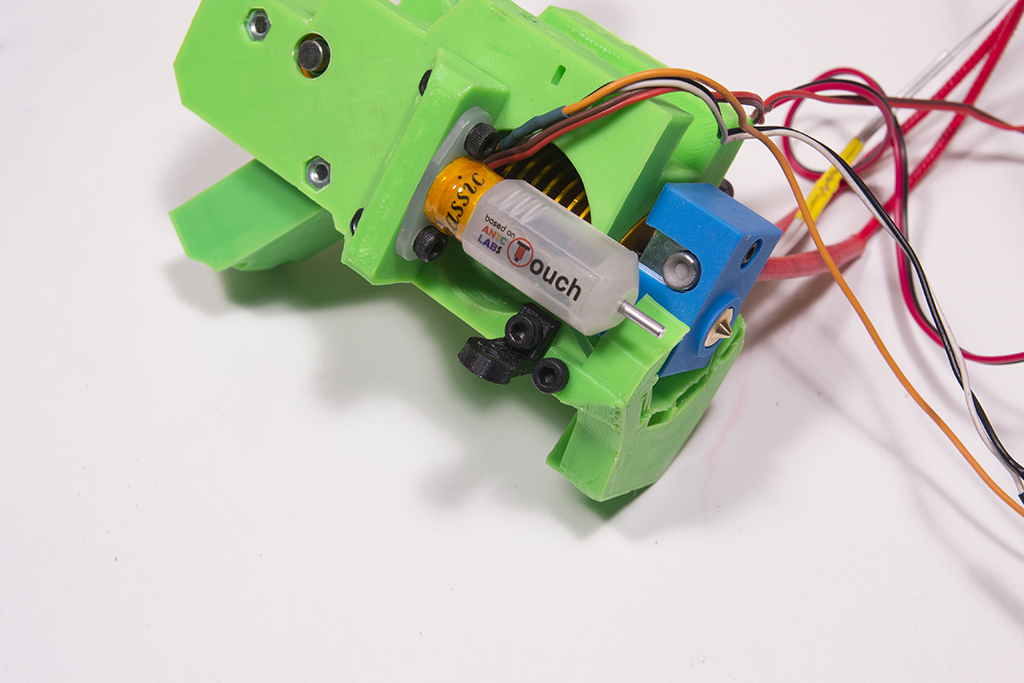
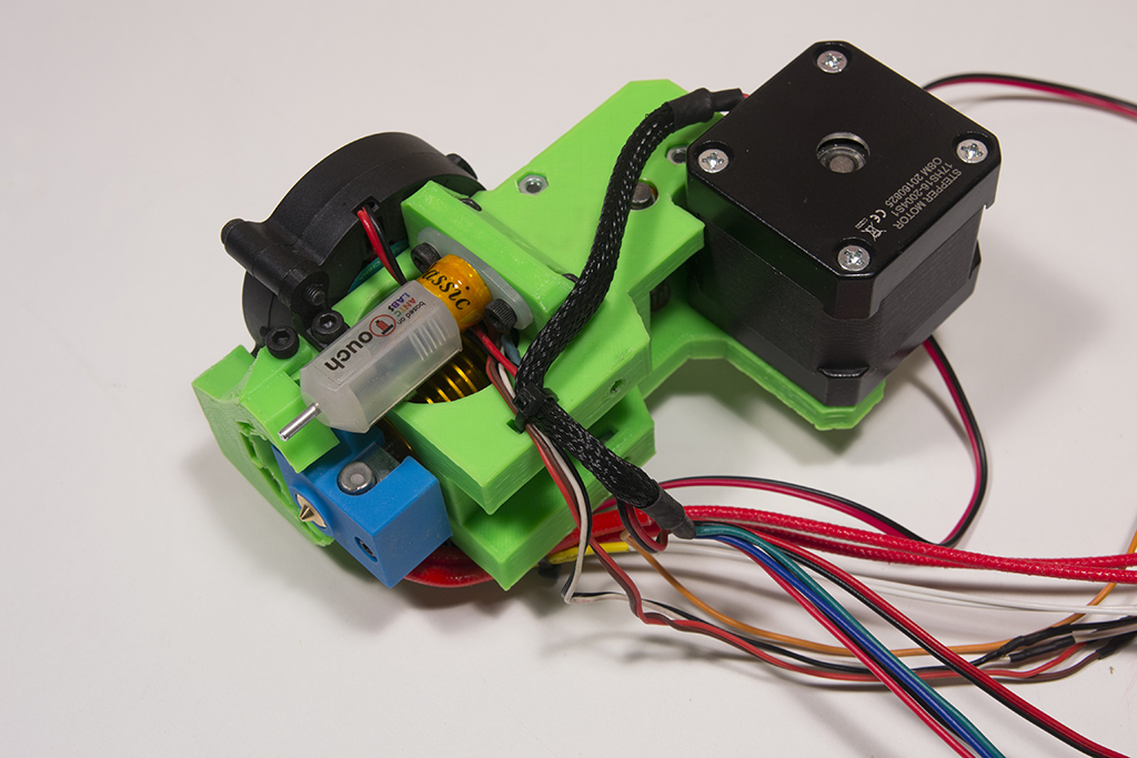
We screw the BlTouch to its support
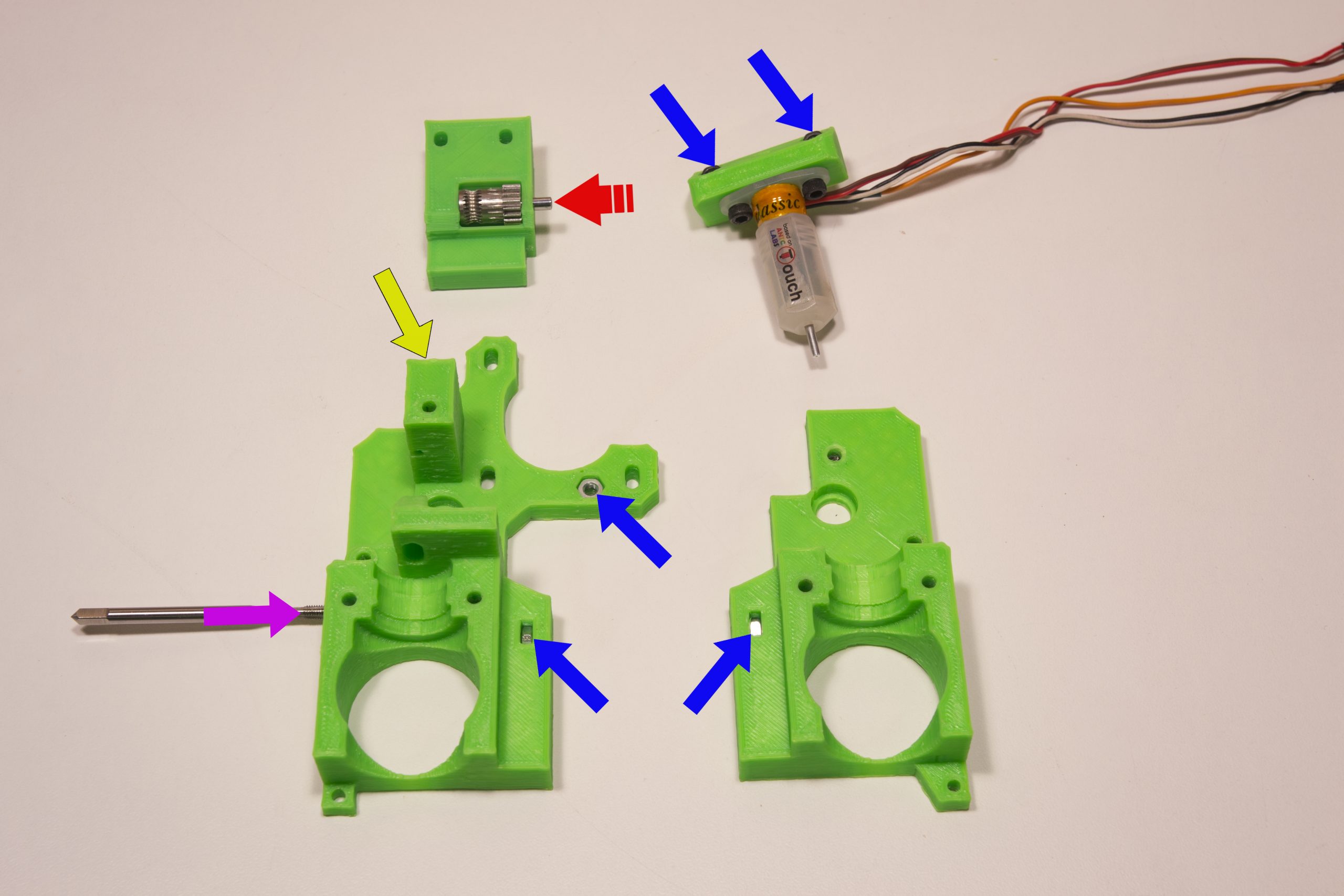
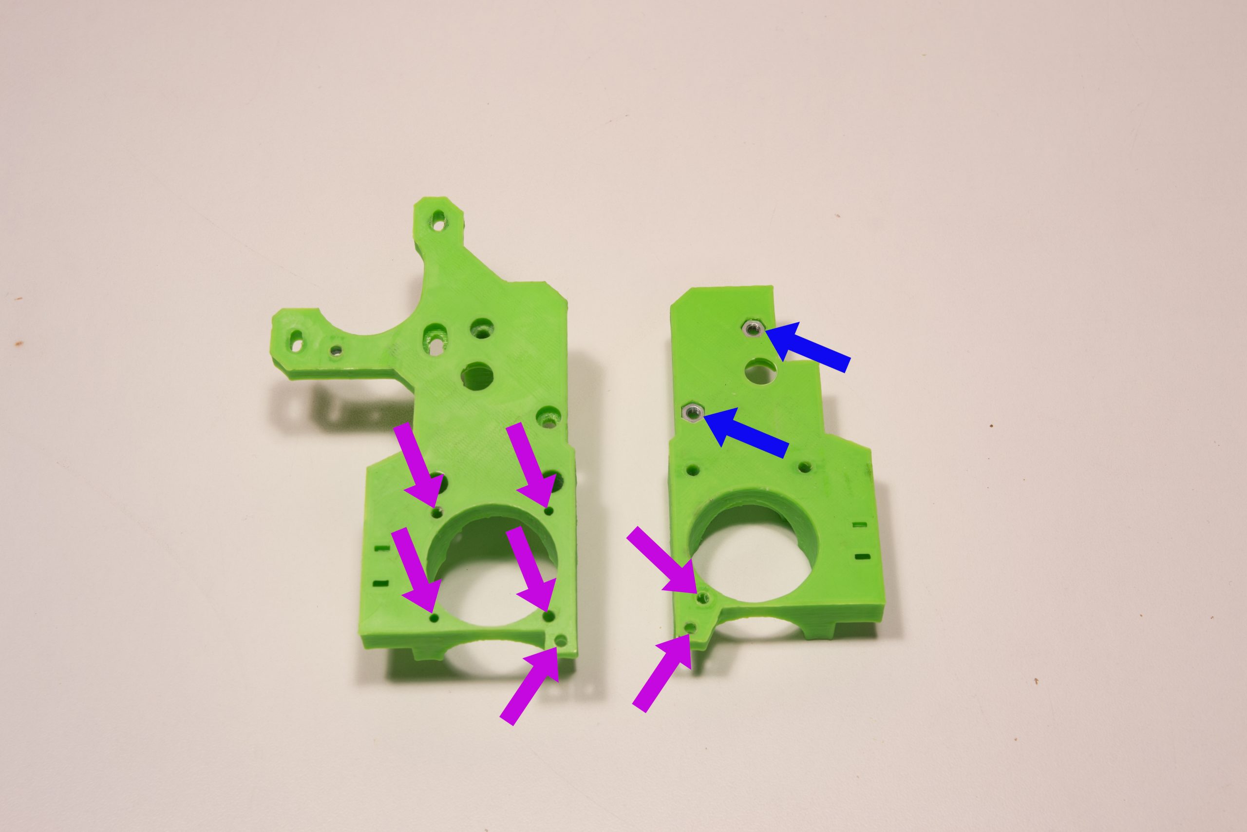
M3 nuts are fitted in the slots marked with the blue arrows
We tap M3 the holes indicated by the purple arrows
We cut about 50mm of PTFE tube which we push into the heating head
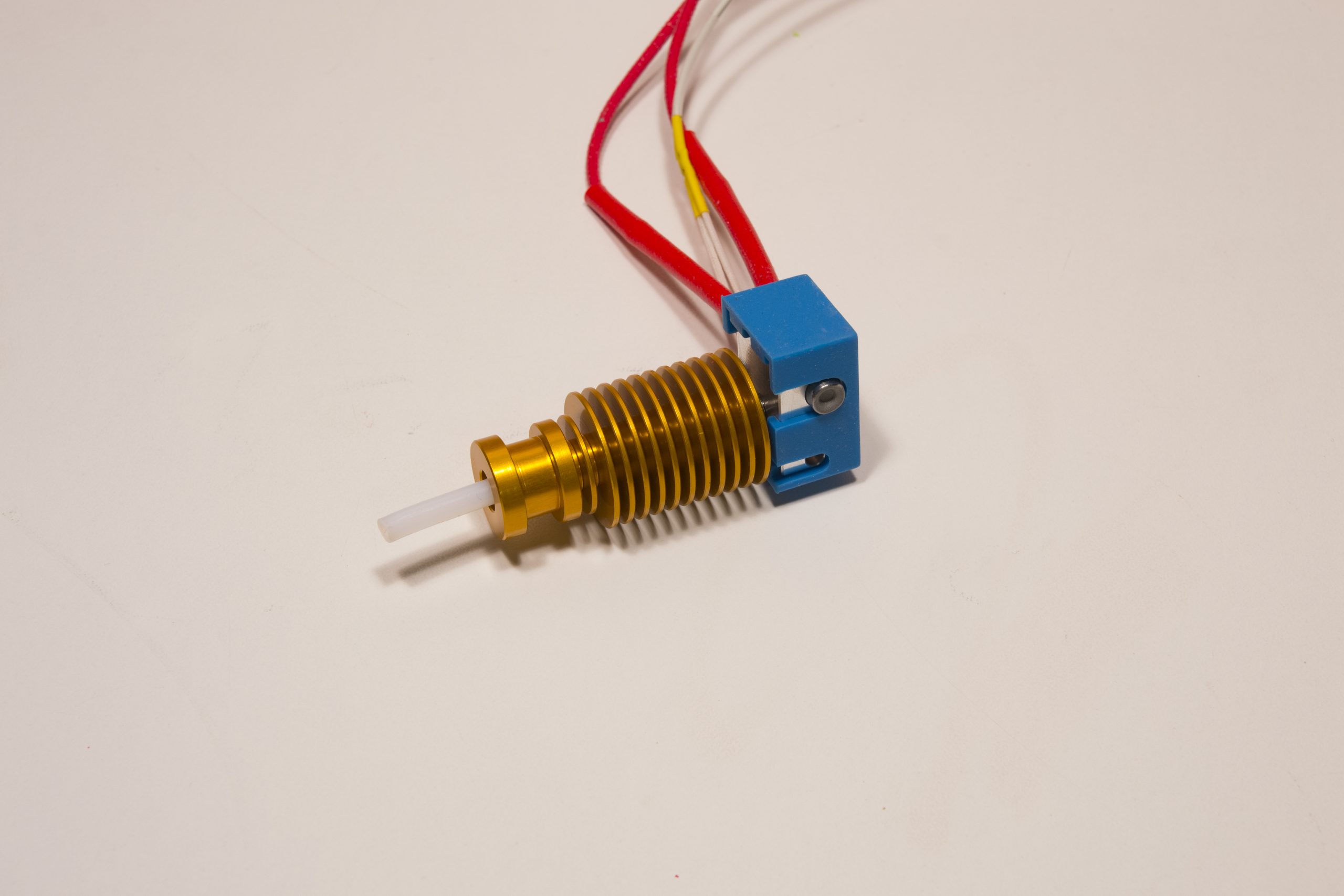
We put everything in half of the extruder and we cut the PTFE which exceeds

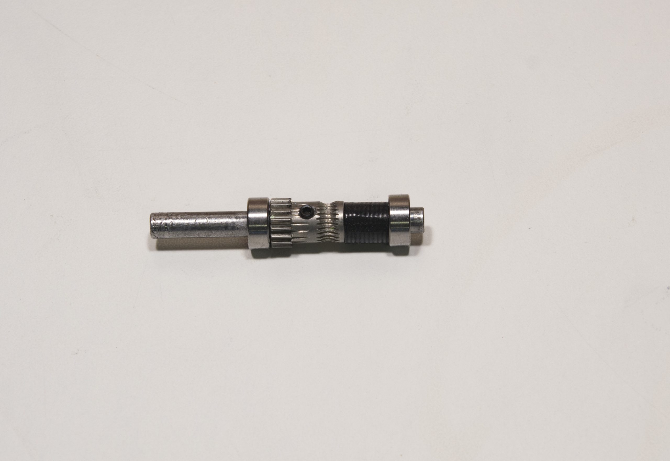
The axis is prepared by threading the drive gear, the printed spacer, and the two MR105RS bearings like this (do not tighten the screw yet) (It is strongly recommended to file a flat on the axis, just under the screw of the filament drive gear).
We put everything in place in this direction
We put the second half
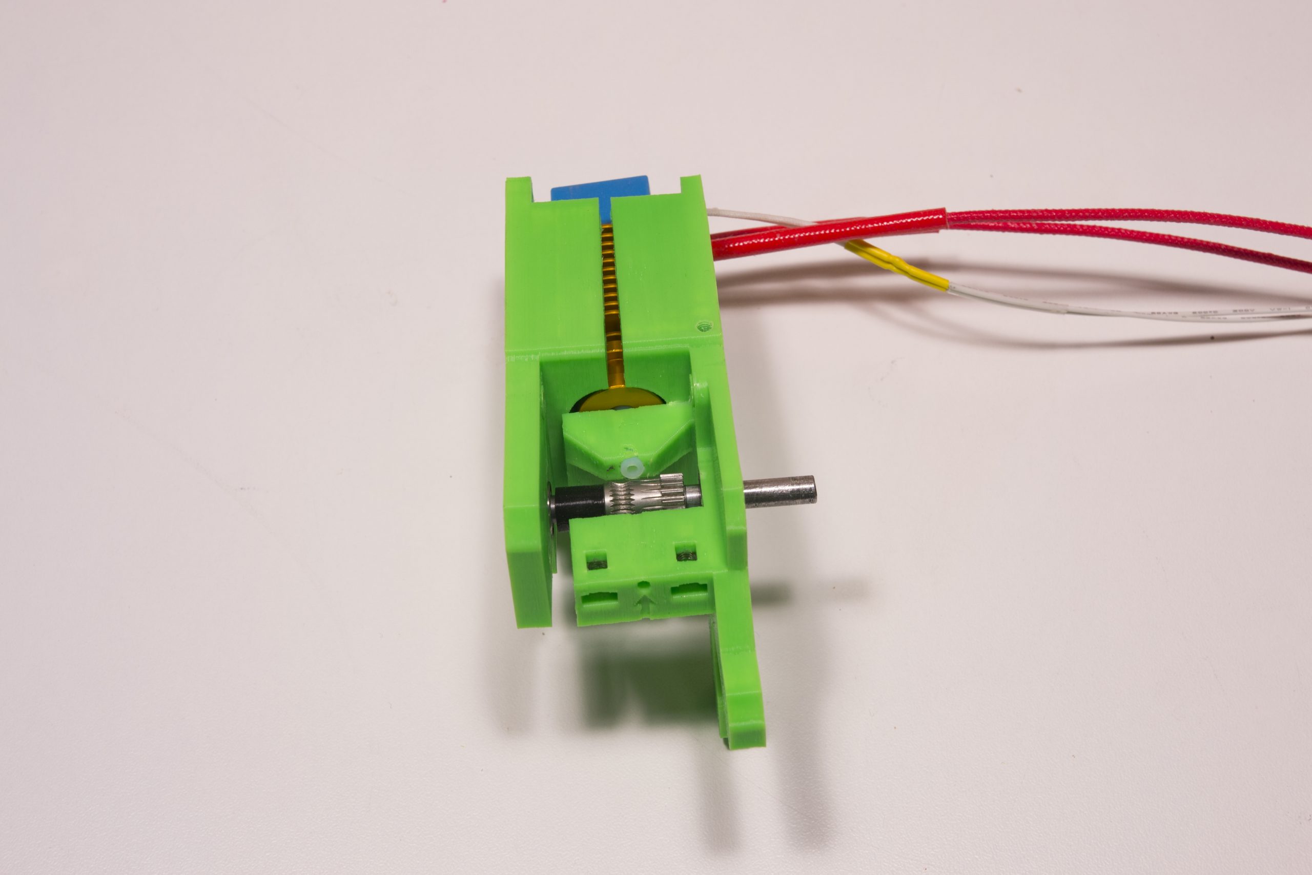
We put two M3x30 screws through the extruder which are screwed on the BlTouch support.
Wait until all M3x30 screws are in place before tightening

Add the extruder idler, and tighten all the screws
We put the 5mm axis flush with the plastic part on this side and we screw the drive gear firmly

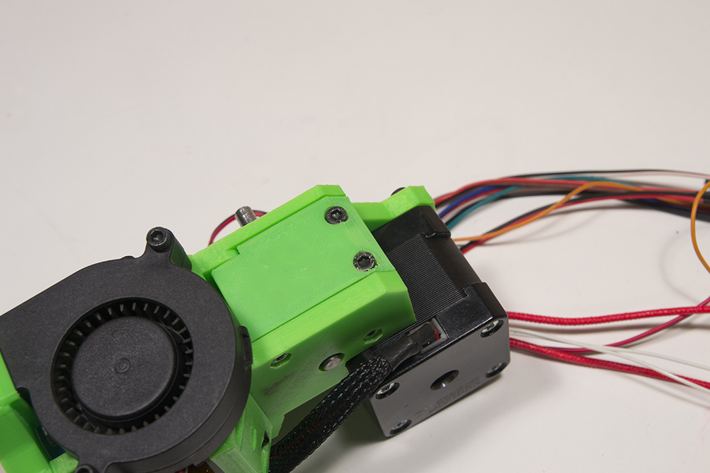
We screw the fan with two M3x16 screws, the fan must blow inwards, so the fan label must be inwards.
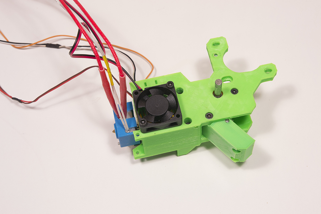
The fan duct is fixed with two M3x6 screws

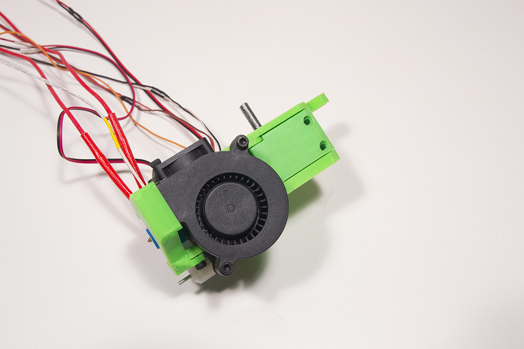
We screw the small part of the radial fan support with an M3x6 screw and tap the other hole M3.
The radial fan is fixed with two M3x20 screws
We put the M3x16 screws on the extruder idler and we can tighten
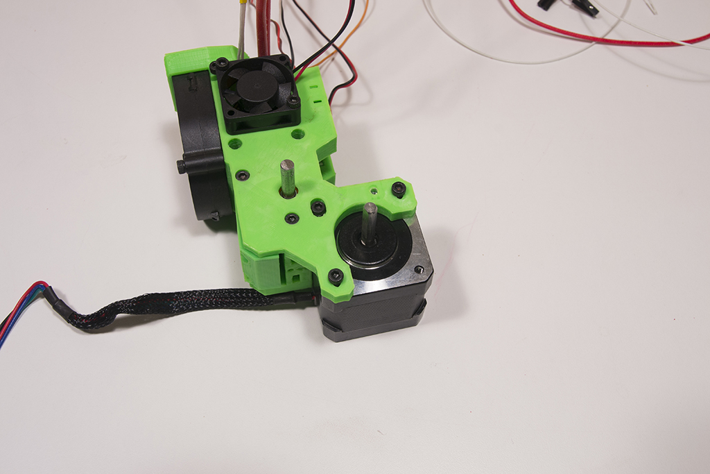
We now screw the motor, the motor cables must be facing forward.
The small motor fixing screw in the middle must be coated with thread locker and must not be fully tightened.
Zip the cables to the extruder on each side thanks to the zip passages provided for this purpose. (Be careful not to tighten the zips too much because the BLtouch cables are very fragile!)
take the pulley 60 teeth, the 16 teeth and the belt 150 and push the assembly on their axis
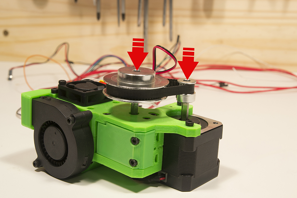
The 16-tooth pulley must not be in abutment against the motor and the 60-tooth pulley must not be in abutment on the extruder, leave a small space and tighten everything
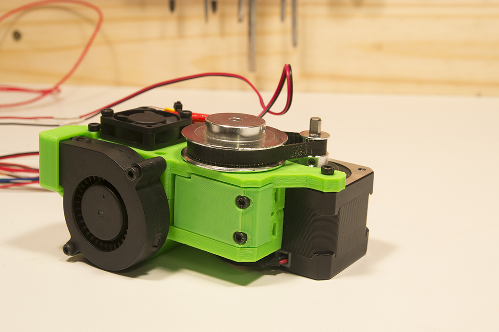
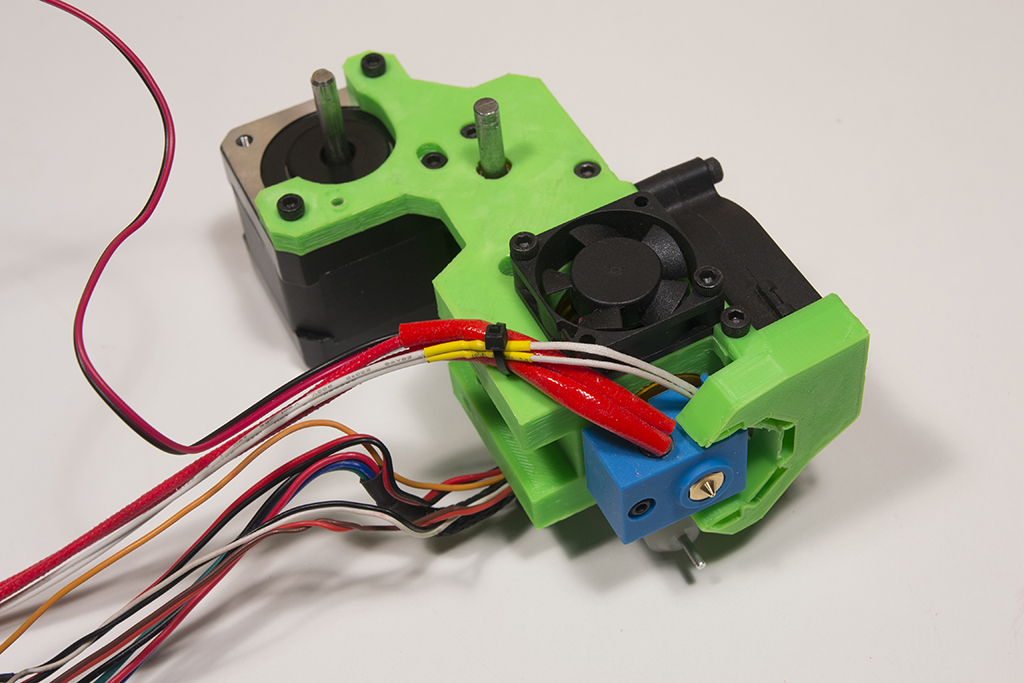
We fix the extruder on the X carriage with two M3x20 screws and an M3x10 screw on the side (blue arrows)
Extend the fan cables
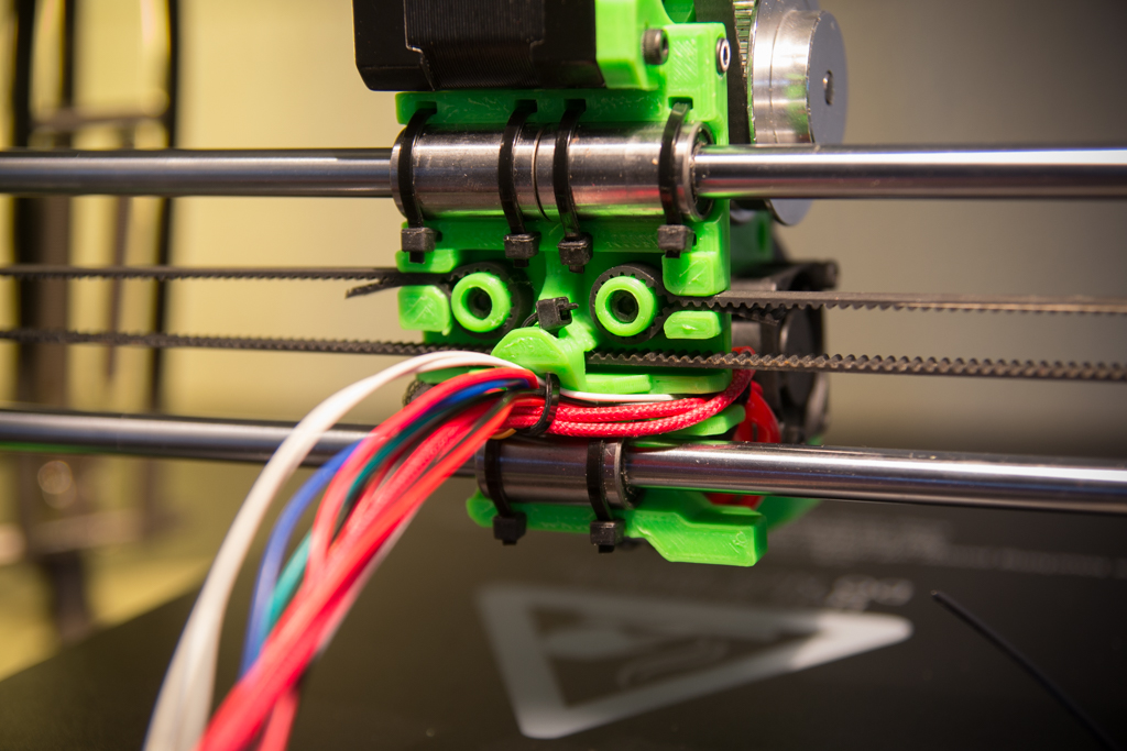
Zip all cables together
TFT assembly
Take the two pieces of TFT support and thread them like this
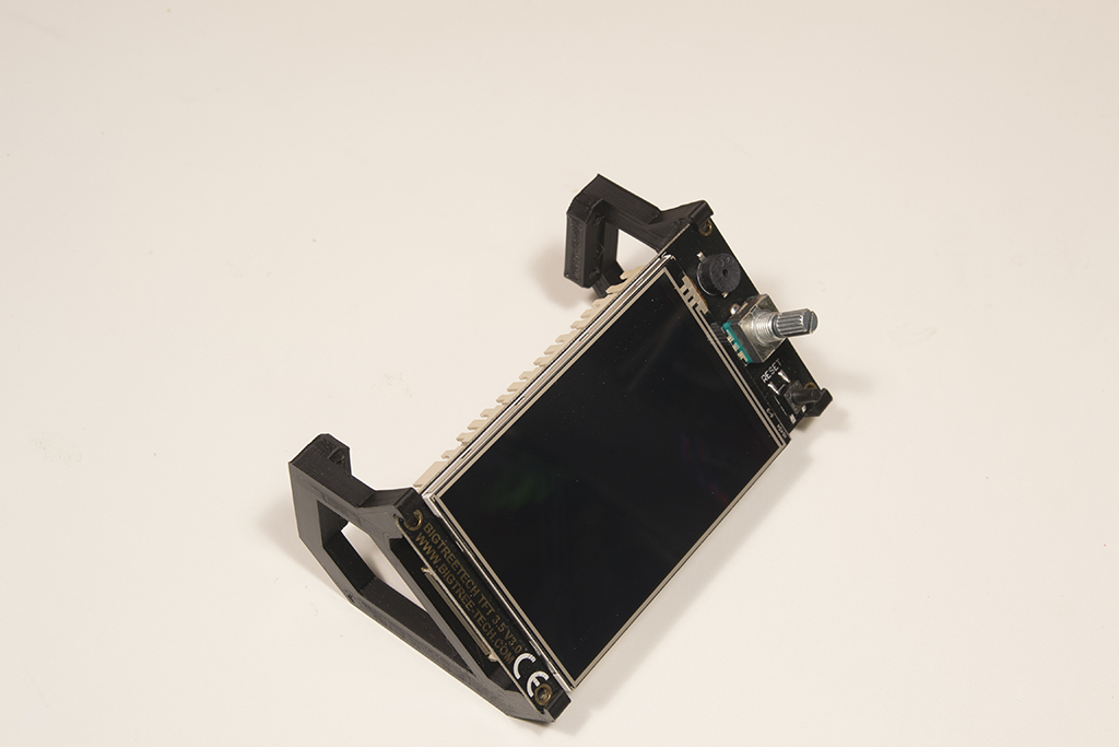
Put on the cover and the button
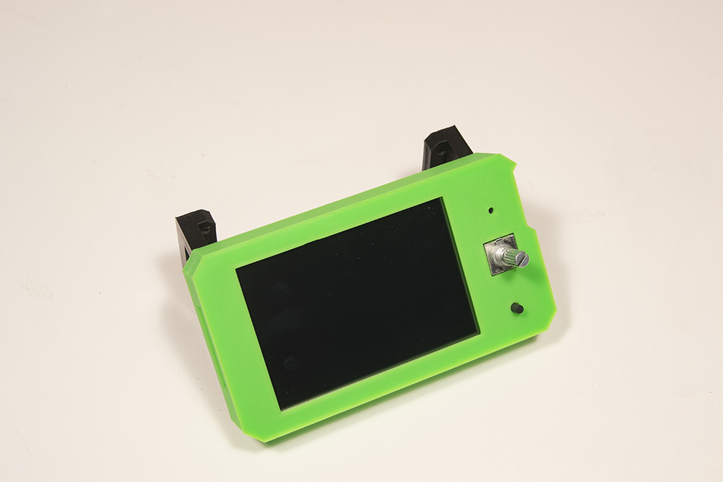
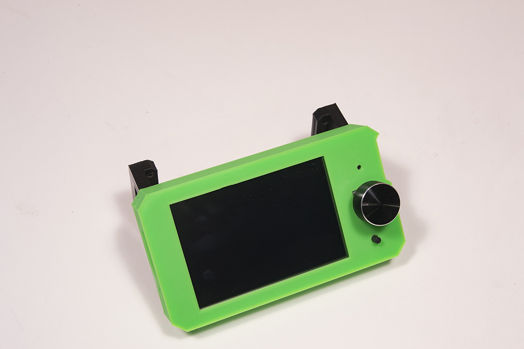
and screw everything to the frame with 4 M3x16 screws

Electronic box
Tap M3 all holes indicated by arrows

Screw the box to the frame using 4 M3x10 screws

To simplify the continuation, already connect the power cables and the heating plate (see next page, wiring) then screw the board in the box.
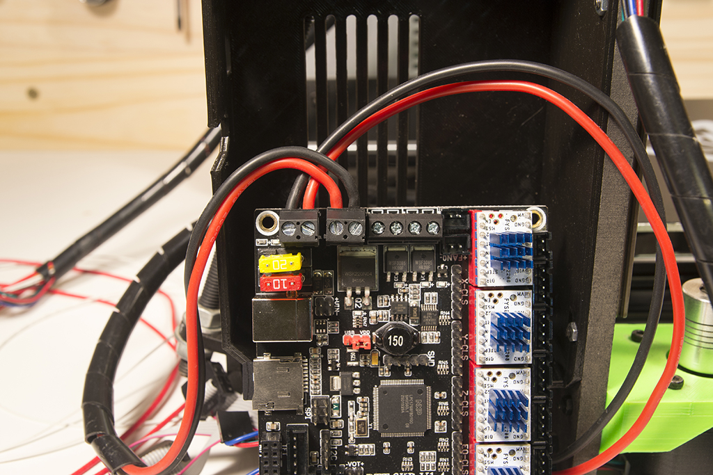

Screw the 40mm fan to the housing cover with 4 M3x16 screws

Rear view when all cabled and cover closed:
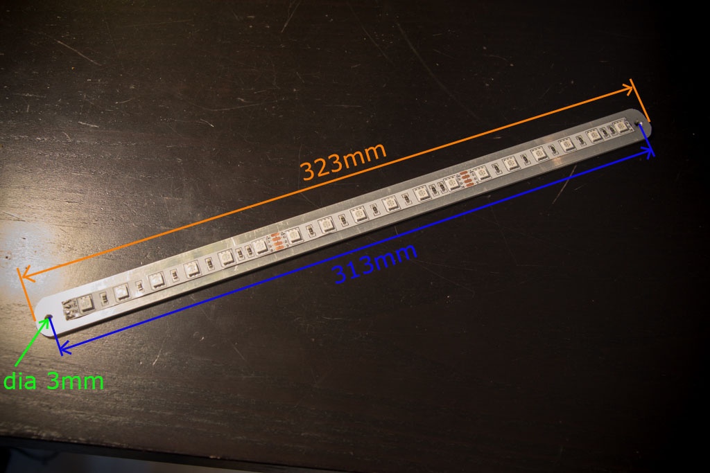
For the led strip, cut a piece of aluminum 323mm long and make two 3mm diameter holes, center distance 313mm.
Voilà ! Go to Wiring