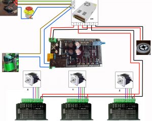
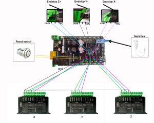
Here are the simplified wiring diagrams for the RS-CNC
1- Power diagram :
The colors of the wires of the stepper motors may vary from one manufacturer to another, check the documentation of your motors to know which color correspond to the wires A +, A-, B +, B-
Note: For added security, you can connect the aluminium box screed (those with the power plug and the emergency stop button) to the ground.
2- Command diagrams :
To connect the Nunchuk, as there is no key, look in the socket, you have a side with 3 contacts, and the other with two contacts, they must of course correspond with the tracks of the plug of the shield .
Note: The nunchuk must be plugged in for the machine works normally.
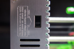
Think before the first power up to check that your power is set to the voltage of your country!
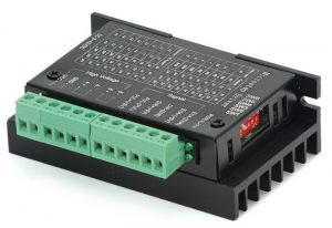
TB6600 drivers settings

- Refer to the printed table on the driver to know the proper position of the small levers on the side of the driver.
- Set the steps in 1/4 steps (no difference in result with 1/16 setting).
- Adjust the amperage according to the data sheet of your motors.
Check your connections several times before the first power up, then go to the firmwares page


Hi,
Thanks a lot for sharing your GREAT project.
Actually I´m printing all parts and preparing the electrical stuff.
Is it possible to use additional sensors (e.g. tool length sensor or automated edge finder / zeroing) on your shield (https://www.makerfr.com/en/shop/shield-rs-cnc/)?
Looking forward to your response and remains with best regards,
Christian
Hi Christian,
This cnc has made to be most simple as possible to use, i don’t know why you would add sensors.
Romain
Bonjour Romain,
Peux tu me dire sur quelle borne qui sont derrière l’écran(TFT 32) dois je brancher ?
Merci
Bonjour Gérard,
Il faut brancher la prise “aux1” du TFT
Romain
Bonjour Gérard,
J’ai eu le même problème il faut brancher le TFT sur aux1 et l’alimenter en 24v. ça ne fonctionne pas avec juste l’arduino raccordé sur le pc en usb.
bonne journée
Stéphane
In the TB6600 driver I don’t see the option for 1/4 steps. It only shows options like 1-200, 2/A-400, 2/B-400… which one is correct for 1/4 steps. Thanks!
Hi Ismael,
1/4 is “microstep” -> 4 , “pulse rev” 800
Romain
bonjour,
désolé si il y a un doublon de message je sais pas si le 1er est posté,
j’essaye d’installer le firmware mais étant sur l’anceinne version tous mes drivers sont configurés pour l’ancienne
que faut modifier pour ne pas toucher les réglages de mes drivers ? car il ne fonctionnent pas en 1/4
merci d’avance
Hello,
Dans configuration.h il faut trouver les lignes:
#define XAXIS_STEPS_PER_MM 240
#define YAXIS_STEPS_PER_MM 240
#define ZAXIS_STEPS_PER_MM 1600
et changer les valeurs
Romain
Hi RoMaker,
I bought the CNC shield from your shop and I have one problem: on the pins marked with 5V I don’t have 5V unless I connect arduino to an USB source (PC or other source), any idea how to fix this ?
Best Regards,
Stefan
Hi,
If you don’t have 5v at the 5v pin, please check your arduino mega 2560 board !
5V pin on the shield uses the 5v power from mega2560 regulator.
The 5v regulator on the shield is used to power only the tft, not the 5v pin.
On your wiring diagram the gnd pins (ENA- / DIR- / PUL-) are connected on -5V on that pin on shield, and the drivers don’t work, if I connect an usb cable to arduino then all it’s ok, can I take than GND from another source ?
Hi, Ena-, Dir-, Pul- of the TB6600 have to be connected on the GND pin of the shield.
If you still have issue, please create a post on the forum (international section) with pictures of your wiring.
Romain
Bonjour Romain,
question pour réaliser les divers branchements sur les pins du shield faut il acheter des connecteurs particuliers?
Hello Pierre,
oui il faut des connecteurs “dupont femelle 2.54mm”
Romain
Salut, je projette d’utiliser un spindle, mais du coup pour le contrôle de la vitesse, ça se passe comment ? Le câblage diffère ? le shield et le firmware n’ont pas à être adapté ?
Bonne journée 🙂
Bonjour,
Tout dépend du spindle utilisé ! Est-ce un spindle avec un potentiomètre ou avec un module de gestion de la vitesse PWM ?
Romain
Bonjour,
La réponse à la question “avec un module de gestion de la vitesse PWM” (0-10V) m’intéresse. Cela est possible avec la shield ?
Oui c’est possible mais là je suis en train de sortir une carte autonome 32bits GRBL avec TFT, ça surpasse de loin le shield actuel et l’ensemble de l’électronique est encore moins cher !
Regarde le sujet en cours 😉 https://www.makerfr.com/forum/viewtopic.php?f=26&t=6023&start=340
Romain
Je vais prendre celui que tu as listé avec les pièces, il devrait être largement suffisant ^^ je ne sais pas encore si je prendrais sur AliExpress ou banggood.
Bonjour,
Je suis en cours de programmation de la carte Mega, tout est OK mais je voudrais vérifier l’avance en mm sur X,Y,Z. Dans “Configuration.h” de REPETIER FW je ne trouve pas les lignes concernées.
Je suis en 1/8 de pas sur les drivers. Dons si mon calcul est bon cela doit faire moteur 200 pas et poulies préconisées (60 et 20 dents) donc rapport 1/3.
X et Y = 400
Z = 800
A moins que les valeurs soient indiquées d’origine auquel cas, je n’y touche pas.
Merci
Edit: J’ai trouvé mais d’origine elles sont sur
X et y = 60
Z = 400
Hello, d’origine le firmware est paramétré pour du 1/4 de pas, donc en 1/8, il suffit de doubler les valeurs d’origine !
Romain
Merci je regarde ça.