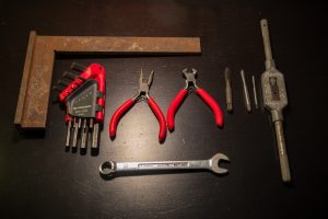
Tools list:
A set of BTR keys, pliers, cutting pliers, a spanner of 13, taps M3, M5 and M8 with a turret, a square, a soldering iron with tin and heat shrink and finally a drill.
Frame assembly
After having cut the V-slot aluminum profile to the correct length with a perfectly perpendicular cut, tap at M5 all the holes at the ends of the profiles (16 holes in all). Attention, Vslots profiles of some suppliers tapped M6 and suddenly it will be necessary to use M6x20 screws and enlarge the holes of the frame to 6mm.
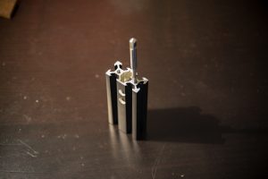
And drill two 8mm holes as in the picture on the two profiles. It’s just to pass the cables through the profiles.
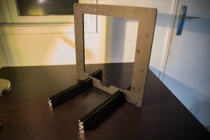
Hand tighten, without tightening, the aluminum profiles to the frame.
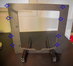
At the back of the frame, push the M3 nuts into their 8 slots
Insert M3 nuts into the Y reinforcements slots
And slide them into the V-slot rails (top groove)
Insert into the Vslot rail the green piece (bottom groove)
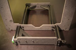
With the M5x20 screws screw the corresponding frame parts to the front and back, do not forget the Z reinforcement at the right rear as in the picture.
Once all parts of the frame are assembled, make sure you are on a flat surface and tighten all M5 screws, the 6 feet of the frame should be on the ground.
then screw the Y reinforcements with M3x16 screws
Insert M3 nuts into all the slots of these parts (to insert the nuts into the rectangular slots, help yourself with the needle nose pliers)
Screw the pulley with the M3x25 screws and screw the switch with two M2x10 screws (wired on the NO and C terminals, and remove the blade by pulling on it)
Screw the Y pulley module with two M3x20 screws, but do not tighten, instead, leave space between the workpiece and the frame.
Screw and tighten the Y smooth rods support parts at the front and back with M3x12 screws
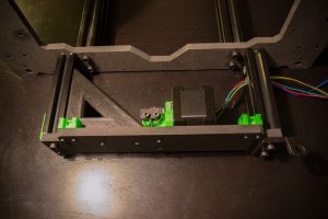
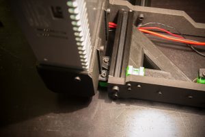
Screw the Y motor to its support and add the 16-tooth pulley and the wired switch to the NO terminals with two M2x10 screws like this:
Screw the assembly on the back of the frame
On the front side, screw the” Z bottom” brackets
Before fixing the slides MGN12, clean them well with a cloth because they are often delivered sticky, then coat the grooves with fine oil, there should not be a big point nor game. And attach them to the frame without them. tighten for the moment with 8 screws M3x10
Tape M8 BackCorner
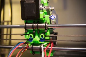
Screw on the M8 threaded rod and insert two M3 nuts marked by the blue arrows.
First we put the threaded rod in the bottom piece, then we screw the top
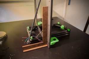
Play on the M8 nuts so that the frame is perpendicular to the ground (always on a flat surface)
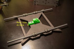
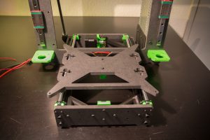
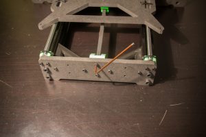
Take heatbed support and zip the 4 LM8UU bearings in the middle of their housing, screw the piece Y_Belt, the long side of this piece goes to the back of the machine.
Clip the assembly pressing the end of the rods and then zip them to their support
Put the Y belt
Tighten the screws of the Y pulley module, check the tension of the belt, it should not be too loose or too tight, if it is not the case, repeat the operation until you have the correct tension.
Power supply assembly
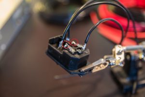
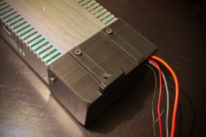
Take the electrical plug and switch module, weld the surrounding parts in red and solder the cables, then put heat shrink at the welds.
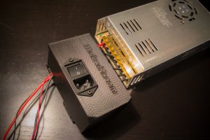
Screw the plug module into the plastic holes without nuts with two M3x8 screws
Connect the phase, the neutral and the ground, then a pair of 16AWG cables on the 24V out that will feed the MKS Base and a pair of small section cables that will feed the RGB leds strip.
Screw the base of the power supply with 3 screws M4x8
On the front attach the power supply with two M4x12 screws and then on the back with two M3x16 screws
X / Z module assembly
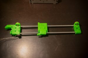
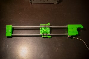
For the Y axis, tighten the copper nuts of the leadscrews with 6 M3x12 screws, the X pulley with a M3x16 screw and a nut, the switch wired to the NO terminals with two M2x10 screws.
Zip X-dolly on LM8UU bearings, and put a gap of about 306mm between the end pieces.
Put a little threadlock on 8 screws M3x20 and screw all on the slides by tightening moderately.
Check that the Z-assembly slides well, then slide the X-carriage at the top of the Z-axis and tighten the screws at the top of the slides, place the X-carriage at the bottom of the Z-axis and tighten the screws at the bottom of the slides.
Screw the Z motors with 8 M3x10 screws, and screw the 5mm / 8mm couplers.
Put the leadscrews and tighten them in the couplers
Put the X motor in position with a single M3x16 screw for the moment, as in the pic
Put the X belt
Put the other screws, check the tension of the belt, it should not be too loose or too tight, if it is not the case, repeat the operation until you have the right tension.
Heatbed assembly
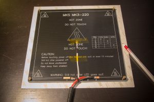
Take your heatbed MKS MK3-220 and screw the 4 standoff 6-32 M3 in the 4 holes of the corners of the board.
Solder a pair of 16AWG cables to the 2 (+) and 3 (-) contacts for a 24V connection.
Glue the probe with kapton tape (heat resistant)
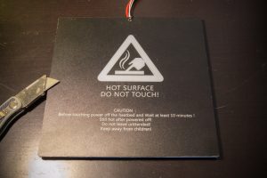
Take a bed liner and trace the outlines with the pen and cut it a little larger than the tray size
Glue the liner on the tray and cut what’s over with a good cutter.
Then fix it to the bed support with 4 screws M3x12
Extruder Assembly
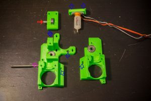
M3 nuts are inserted in all locations marked with blue arrows
Tap the hole on the side indicated by the purple arrow
Put the bearing 625 in the flap of the extruder and slide its axis (red arrow)
The two bearings 625 are nested in their housing
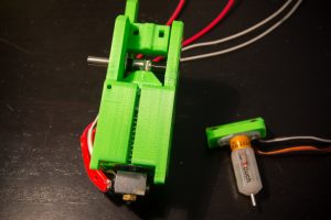
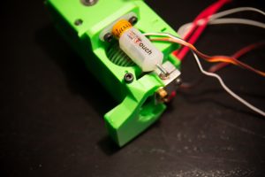
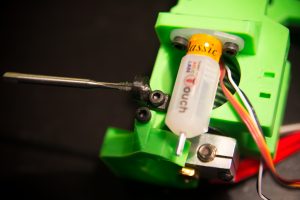
We screw the BlTouch to its support
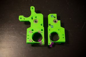
M3 nuts are inserted into the homes marked with the blue arrows
M3 tap holes marked by purple arrows
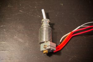
About 50mm of PTFE tube is cut into the heating head
we put everything in half of the extruder and cut the PTFE which exceeds
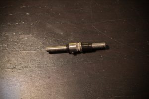
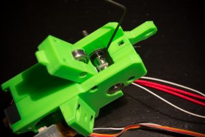
We prepare the axis by threading the extruder gear and the two spacers like this (do not tighten the screw for now)
We put everything in place in this direction
We present the second half
Two M3x30 screws are passed through the extruder and screwed onto the BlTouch holder.
Wait until you have put all the M3x30 screws in place before tightening
We add the flap, and tighten all the screws
We put the 5mm axis to the edge of the plastic part of this side and we screw firmly the drive roller
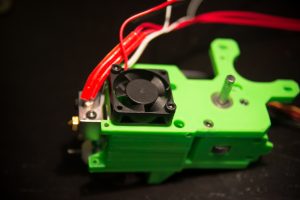
The fan is screwed with two M3x16 screws, the fan must blow inwards, so the fan label must be inward.
We fix the fan duct with two screws M3x6
We screw the small part of the radial fan support with a M3x6 screw and we tap M3 the other hole.
The radial fan is fixed with two M3x20 screws
We put the M3x30 screws and the springs on the flap
Now screw the motor, the motor cables must be forward.
The small mounting screw of the middle engine must be threadlocked and must not be fully tightened.
Zip the cables to the extruder on each side thanks to the zip passages provided for this purpose.
take the pulley 60 teeth, the 16 teeth and the belt 150 and press the assembly on their axis
The 16-tooth pulley must not be against the motor and the 60-tooth pulley must not stop on the extruder, leave a small space and tighten it all
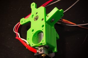
We just fix the extruder on the carriage X with two screws M3x20 and a screw M3x10 on the side (blue arrows)
Extend the fan cables
Zip all the cables together
TFT touch screen assembly
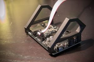
Take the two TFT support pieces and thread them like this
Connect the plug in the same way
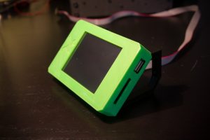
Put the cover
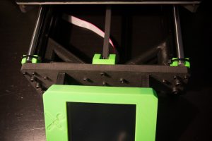
and screw everything to the frame with 4 screws M3x16
Electronic box
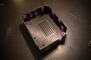
Tape M3 all the holes indicated by the arrows
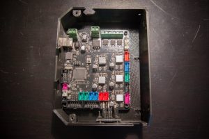
Screw on the MKS Base 1.5 board and the RGB leds module with 6 M3x6 screws
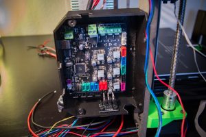
Screw the set to the frame with 4 screws M3x10
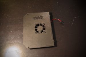
Screw the 40mm fan to the box lid with 4 M3x16 screws
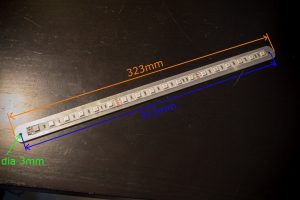
For the led strip, cut a piece of aluminum plate 323mm long and make two holes diameter 3mm, spacing 313mm.
Voilà ! now we go to wiring








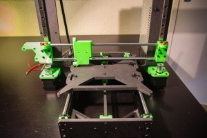
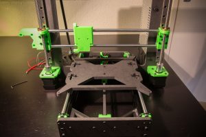
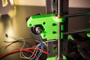

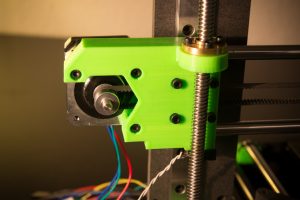






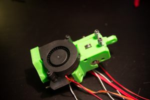
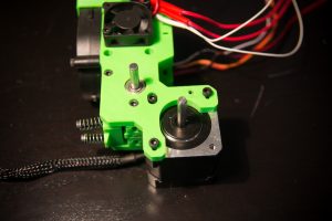


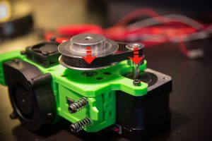
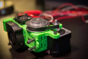



Bonjour, un petit souci lors du montage de la tête et de l’extrudeur,
lorsque j’essaye de mettre La poulie 16 avec la poulie 60 dents et la courroie 150 le moteur nema ne reste pas dans l’axe comme si la courroie était trop petite ou autre chose (j’ai essayer avec 2 courroies différentes donc je ne pense pas que cela soi ça) avez vous une idée de solution ?
je vous ai mis des photos pour que vous puissiez mieux comprendre
https://ibb.co/bDsaEx
https://ibb.co/cYBVgc
merci
Oulà oui là c’est un peu trop !
à mon avis les trous oblong de la fixation du moteur sont mal ébavurés , et si ce n’est pas la cas, il faudrait allonger les rainures vers le bas avec une petite lime… mais première fois que je vois ça !
Romain
bonjour,
juste pour infos c’était juste la taille de la Poulies gt2 16 dents qui était trop grosse … j’en ai recommander d’autre et la plus de souci
merci
Bonjour Fabrice,
Même problême pour moi !
Pourrais tu mettre le lien de la poulie que tu a pris stp ?
Merci
Hello!
Je suis en train de commander les pièces. Histoire de ne pas commander une mauvaise, est-ce que celle listée est finalement correcte ou est-ce qu’il a fallu en utiliser une autre? Si il a fallu changer, pour quel modèle?
Merci!
Bonjour Simon, je te répondrais avec plaisir, mais je ne sais pas de quelle pièce tu parles ^^
Romain
Salut Romain!
Il s’agit de la poulie gt2 16 dents pour l’extrudeur citée comme trop grosse par Fabrice le 11 avril. Tout comme Julien, j’aurais aimé savoir quel modèle Fabrice a pris pour éviter le soucis.
Belle journée!
Simon
Hello,
En fait le problème est qu’il avait commandé une poulie 20 dents et pas une 16 dents !
Hello,
Je commence le montage de mon imprimante avant d’attaquer la CNC.
A l’étape de l’extrudeur tu parles de préparer un axe qui traverse le roulement, L’axe sort d’où ? Je sais pas si j’ai loupé une étape…
Merci d’avance pour ton aide et encore bravo pour ton travail.
Belle soirée à tous.
Bonjour Steve,
l’axe à préparer est le morceau de tige lisse diamètre 5mm longueur 51mm de la liste des pièces partie quincaillerie.
Bonne journée
Romain
Bonjour, Très beau travail !
J’étudie le montage de la machine. J’ai vu que le sachet de visserie est en rupture de stock. Quand est-ce que ca sera réapprovisionné ?
Bonjour Fab,
Normalement fin de semaine ou début de semaine prochaine, j’attends de me faire livrer les tailles de vis manquantes 😉
bonjour,
Je transforme ma prusa I3 en I3RS, peut tu m’indiquer les côte de perçages a faire sur le cadre d’origine pour adapter les nouvelle pièces svp
Bonjour,
Le plus simple est d’ouvrir avec un logiciel de CAO le fichier DXF du cadre fourni dans le pack de fichiers avec les STL 😉
Romain
merci Romain
Bonjour,
Ma prusa I3RS 😉 a fait ses premiers pas, j’ai garder l’electronique de la prusa avec ta mecanique, encore un chouia de reglage et ça devrait etre nickel; j’ai un peu galérer avec le bl touch et le Z offset, mais c’est le chemin pour apprendre.
bon reste a comprendre Cura, et les subtilités de réglage. Prochainement je referais l’Y aussi selon ta methode, car finalement le vert c’est jolie. Merci pour ton travail.
bonjour, je suis bloqué à l’assemblage du bloc d’alimentation. Quel type/taille de fil (en noir sur la photo) vous utilisez pour câbler la prise électrique/switch ? de plus les photos c’est un peu juste pour comprendre le câblage :-). N’y aurait il pas un schéma de câblage qui traîne ?
Bonjour Arnaud,
J’utilise du câble prévu pour le 220v du secteur, soit du 0.75mm², tu peux en récupérer sur un vieil appareil électrique, il en faut juste un peu.
Le schéma de câblage se trouve à la page juste après “Câblage I3 RS”
Si tu rencontres d’autres difficultés techniques, il serait plus simple d’utiliser le forum.
Romain
re moi :-). En attendant de comprendre le câblage électrique du switch, j’ai monté l’extrudeur. Cependant l’extrudeur que j’ai commandé est plus long d’au moins 1 cm par rapport à celui que l’on voit sur les photos. C’est gênant ou pas du tout ?
à priori oui c’est très gênant, ouvre un post avec photo sur le forum qu’on voit ça
Romain
Hello, je reçois mes pièces petit à petit et je monte gentillement ma machine. voilà je suis peut être bête mais j’ai des soucis pour les câblages de mes Switch de butée car j’ai 3 pôles com no et nc. Et tu dis de brancher un seul pôle genre no. Tu pourrais m’eclairer. Genre y en no nc, x en …. merci par avance de ton retour. Et merci pour mon colis
Bonjour Alexandre,
la borne COM est le commun, NO normalement ouvert et NC normalement fermé, il faut mettre un fil sur COM et un fil sur NO.
Romain
Hello Romain,
le plateau chauffant que j’ai commandé à 2 bornes au milieu sur lesquelles il est possible de souder deux fils, ca ne serait pas déja une sonde intégrée au plateau ?
L’indication derrière est “MKS MK3-220”.
Sinon, je met la sonde de température dans le petit trou ?
Merci,
Will
Bonjour William,
Oui les deux bornes du milieu servent à souder une sonde dans le petit trou du milieu, j’ai déjà testé, mais c’est foireux comme système, il vaut mieux fixer au kapton une sonde filaire comme je conseille dans le tuto.
Romain
Coucou, les supports moteur Z pour les fixer on utilise les vis quelle taille j’ai pas trouvé ? Et l’écrou on le mettra côté support ou à l’arrière ?
Merci d’avance
Bonne soirée
Hello Cédric,
Il faut des 3×16, écrou vers l’arrière.
Romain
Hi guys
I tried a few home kit 3D printers.
All have the same problem that they get in trouble with the heated bed ball bearings.
So I tried out other possibilities to get the issue fixed. Finally I had the best solution with so called ball free bearings, like these: https://www.amazon.de/dp/B01M4JZ81S/ref=cm_sw_r_cp_api_i_6tLGCb83T997D
Perhaps you could also involve that in your printer kit
Best regards
Tom
Hi Tom,
I didn’t get issue with LM8UU bearings but you can order that you want, Igus fit on I3-RS
Romain
juste un petit message pour dire que le travail que vous faites est tous juste monstrueux ,je suis admiratif bravo…sa donne envie.
Merci Karim, ça me fait plaisir ce commentaire 🙂
Bonne journée
Romain