First test print
Insert the filament:
- To insert the filament, cut the end bevel
- Pass the filament through the hole at the top of the extruder keeping the flap closed
- On the TFT screen go to Tools> Filament> InIf the hotend is already at temperature the filament is sucked up and is set up alone! Otherwise you have to wait for the head to go alone temperature 🙂
- To remove the filament we do the opposite, on the TFT screen go to Tools> Filament> Out
Generate his G-code file
- Download a .stl file, for example a calibration set
- We unzip and open the desired file with Repetier
- You can change the layout of the part on the tray (optional)
- Then we go to the”Slicer”tab
- The PLA or ABS preset is selected, “normal speed” print settings, “I3-RS” printer settings.
- We click on “Slice whith Slic3r Prusa edition” and we automatically land on the “print preview” tab
- Now we are ready to print, we have two solutions, either you do it with the printer connected to the computer by clicking directly on “Print” in the tab “Preview print” Or you click “Save” To save your .gcode file that you can put on an SD card that you insert on the right side of the TFT and start printing from the TFT Print> choose the file to print
- There the RGB LEDs turn blue and you just have to watch
Now that this first test is done, to get the best out of the printer, we will make some adjustments:
Drivers voltage setting:
Adjust the voltage of the drivers
Adjusting the voltage of the drivers is essential to the proper functioning of your 3D printer, because too low a voltage may cause steps to be lost during printing and a setting that is too high will make the motors noisy.
The MKS base comes with drivers set too low (below 1 volt), which tends to lose steps with the original settings.
If you have 2A motors, in theory it should be set to 1.6V with the A4982 drivers of the MKS Base, in practice, the good ratio is between 1.2 and 1.4v
To set your drivers you need a multimeter set in “V continuous” and a precision screwdriver, preferably non-conductive (ceramic or plastic), you can use a metal screwdriver but be careful not to slide the potentiometer to not create a short circuit! (same with the tip of the multimeter)
To measure the voltage, put the + on the potentiometer of the driver and the – on the ground, for example the metallic part around the USB port
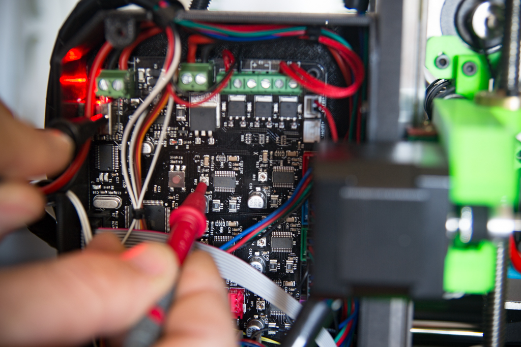
To increase the voltage, slowly turn the potentiometer anticlockwise until you reach the desired voltage.
Repeat for all drivers with the same value if all motors have the same
Offset Z setting :
If your first layer is overwritten or not enough, open the Marlin firmware and look for this line in the “configuration.h” tab:
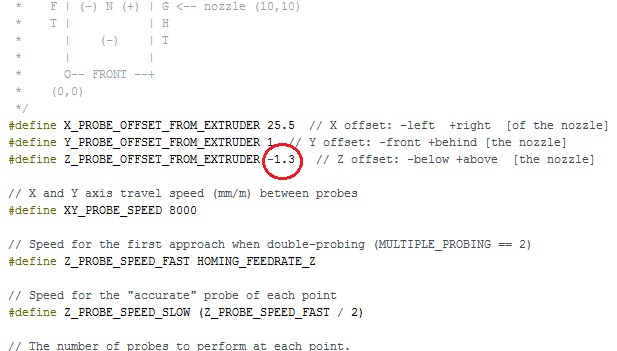
And change the circled value which is the offset in millimeters
Go tenth by tenth, if the filament is not overwritten enough, increase this value, if the filament is overwritten, decrease the value, then upload the firmware back to the MKS Base.
Repeat the process until you have the correct first layer height.
Set the PIDs of your 3D printer
The setting of PID greatly optimizes the print quality, indeed, with PID not adapted to your 3D printer, the extrusion temperature can vary sawtooth, which gives an irregular extrusion and causes a difference in homogeneity visible between layers.
With this little tutorial, you will be able to adjust your PID without difficulty!
The autotune must be done starting from a cold nozzle filled with filament, you can also start the printing fan before starting the test in order to obtain the most precise result possible if you use the cooling during your prints.
- First connect your 3D printer to your computer and turn on the power
- Open Repetier Host and connect to your printer
- In the “Manual Control” tab, enter the following command line:
M303 E0 S200 C8
“M303” is the command that starts the autotune; “E0” is the target organ, here it is the extruder 0; “S200” is the reference temperature for this autotune, it is up to you to indicate the temperature with which you are most used to printing; “C8” is the number of loops for the test, here 8 loops (the more loops you will make, the more precise the results will be)
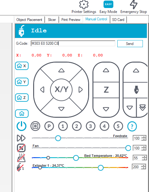
- And click on “Send”
The test starts and lasts several minutes.
At the end of this test, at the bottom of the log you have your new values:
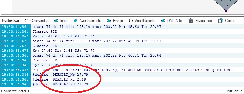
- Note these values and open your firmware Marlin, tab “configuration.h”, search for “PID settings”

- Replace the original values with yours
- Upload on your printer
Your PIDs are set!
Note: It is not necessary to do this for the heating plate because it has a certain thermal inertia that does not have the nozzle, and the temperature variation of the plate does not affect the quality of printing.
That’s it, your printer works, I hope it will give you as much satisfaction as me!
Feel free to register on the forum if you have hesitations of editing or settings, or just to share your editing, it always makes me very happy to have feedback and we start to be a good group friendly and effective 🙂