Before starting the assembly, I just want to give two or three tips for cutting and drilling parts.
Drilling:
- Place the plastic part or printable template on the part to be drilled.
- Using a pencil or a tip, draw the holes to be drilled on both sides of the mason box screed so that the holes are facing each other.
- Remove the template or plastic part
- Point with a needle
- Drill with small front hole (3mm) before drilling to 6mm or more.
Aluminium box screed cutting (It goes of the final geometry of your CNC!):
- Observe precisely the measures
- Draw the cutting line with a square, and on both sides!
- Recheck the measurement after cutting, deburring and filing if necessary.
To tighten the screws through the box screed, go quiet, don’t crush the aluminum, a light tightening is enough, put brake nuts or a drop of brake net. If you really want to squeeze like crazy, you can clap 15mm MDF in box screed ! Personally I have not put and it does not move once the editing is finished, it is not a question of strength but geometry;)
We can start 🙂
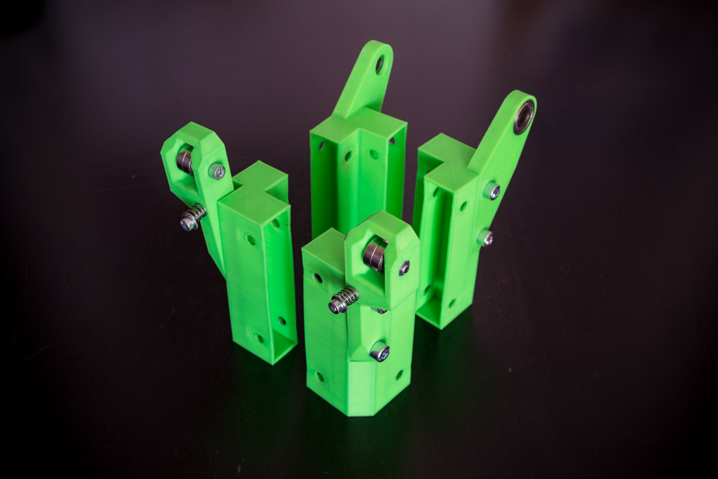
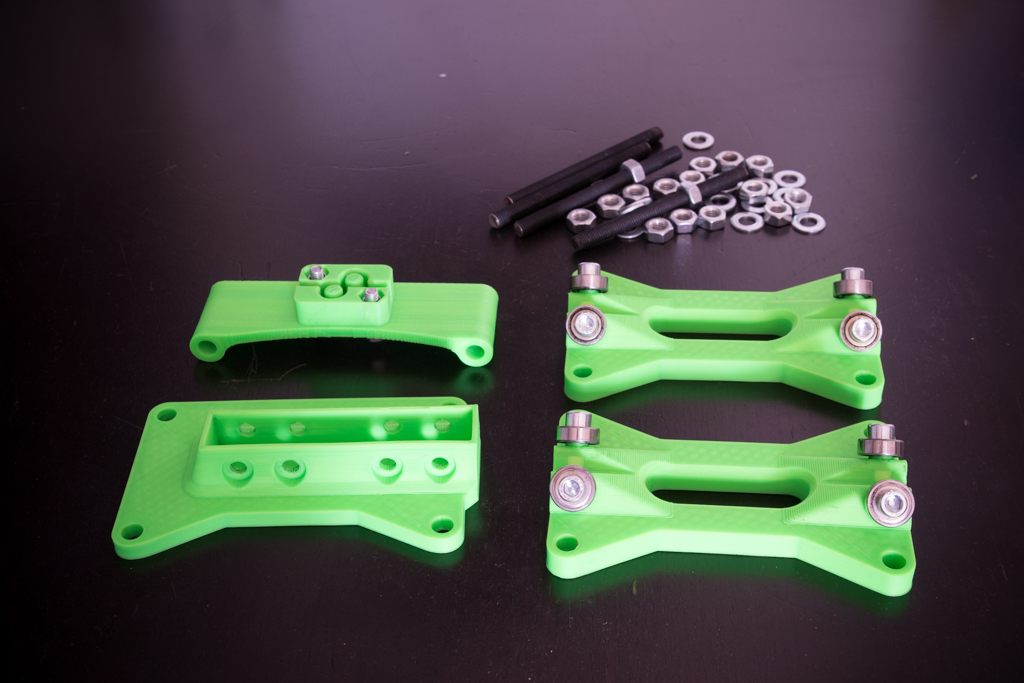
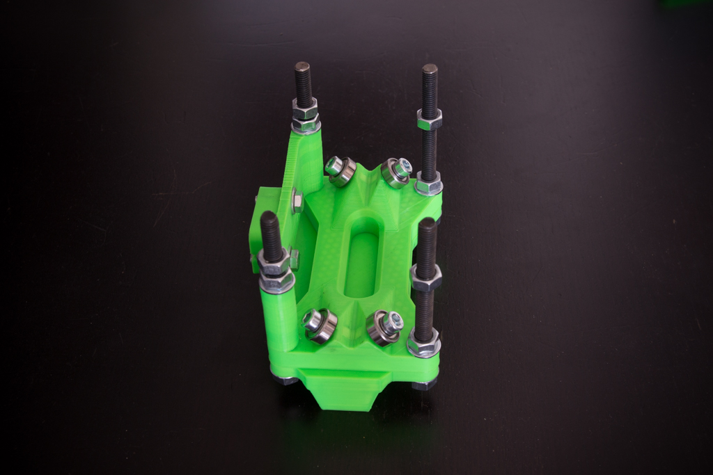
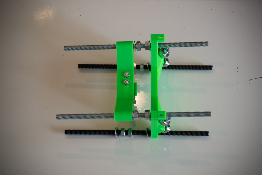
- Take the 4 printable corners and mount them like this with the 2 bearings 608zz for the rear parts, the two pairs of 625zz for the belt tensioners, the two screws m4x40 and the two springs (optional)
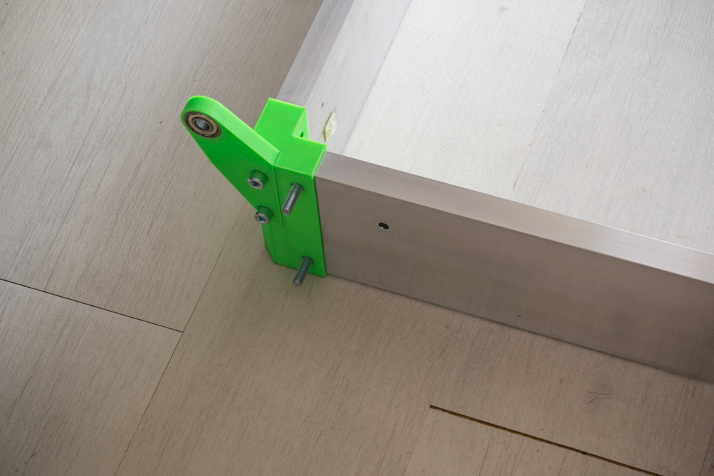
- Take the box screed of 600 and 750mm and nest them like this below then draw the holes on both sides, dislocate the pieces, point and drill at 6mm.

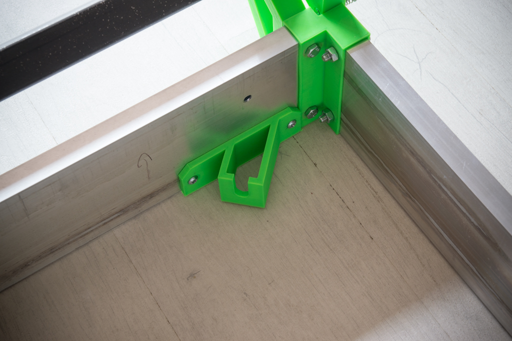
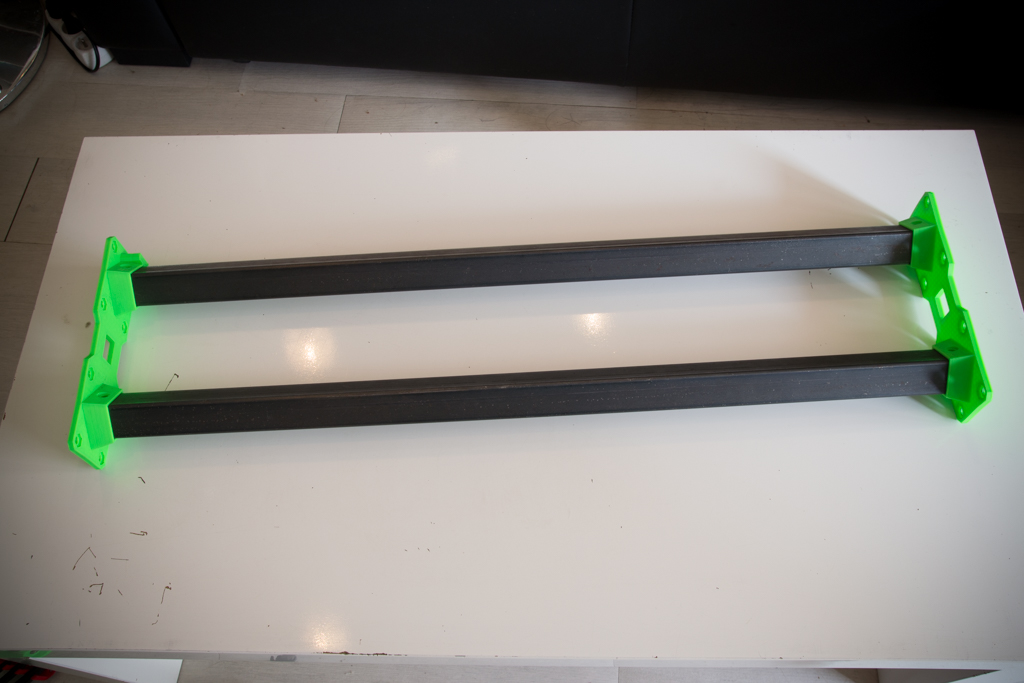
- Take the square tubes of 746mm, nest their supports, trace the holes, point, drill at 6mm, and screw them.

- Insert the 8 screws that hold the Y rail brackets
- Then screw the rail supports at first, then put and tighten the other screws of the 600mm mason rules.
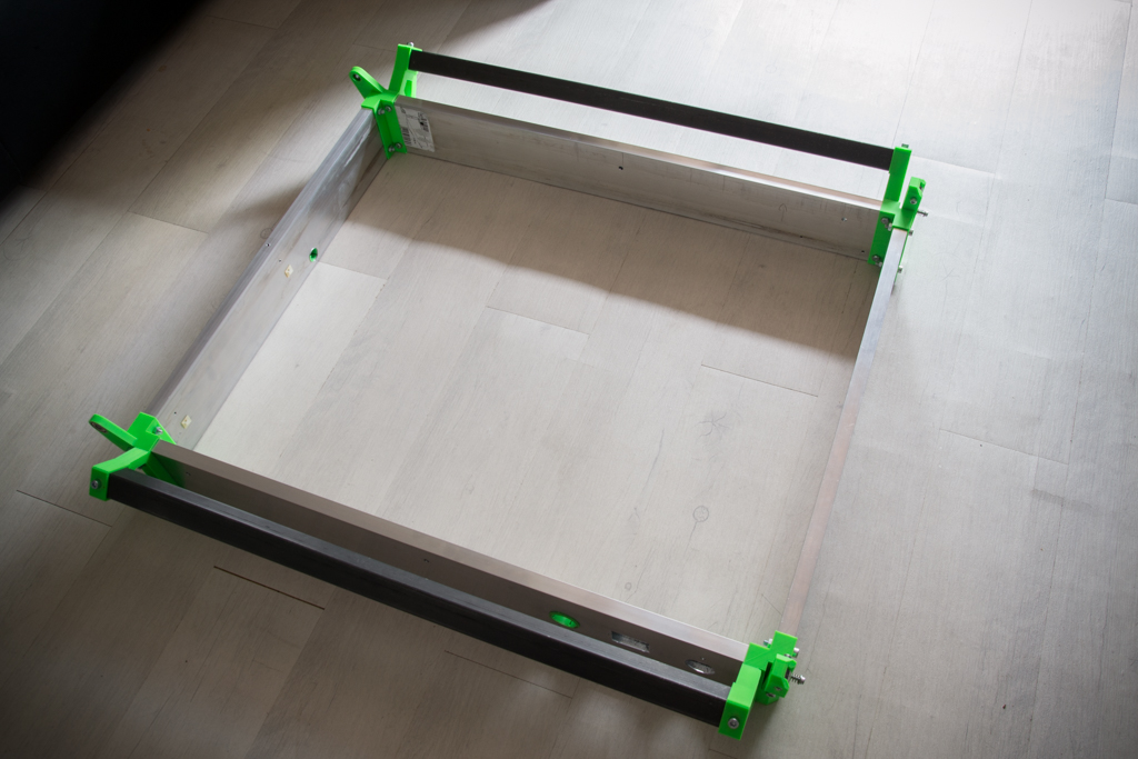
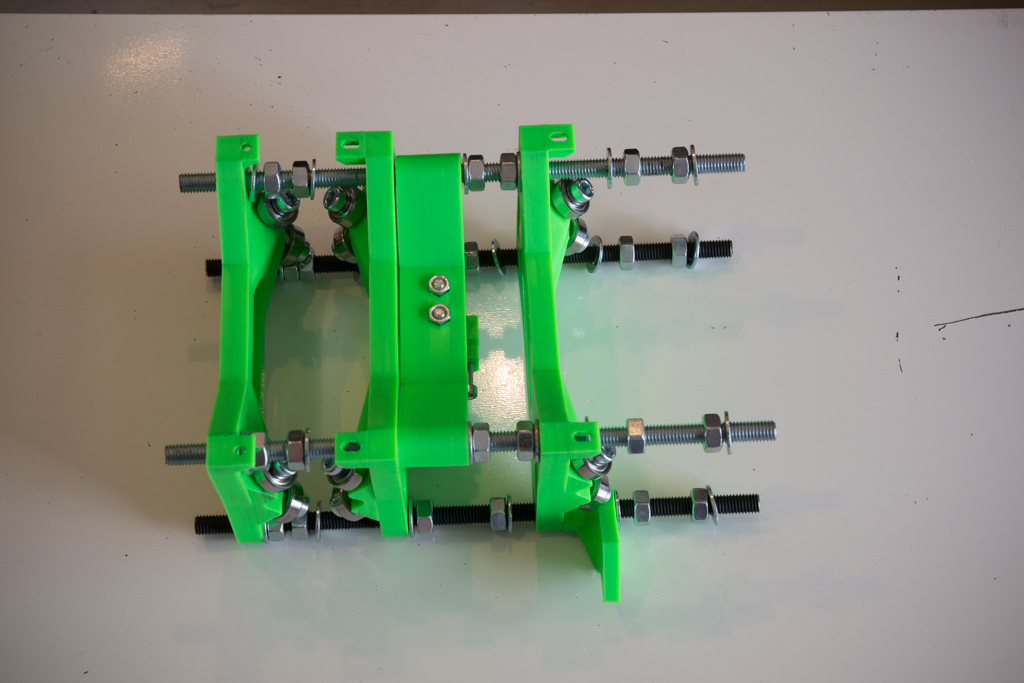
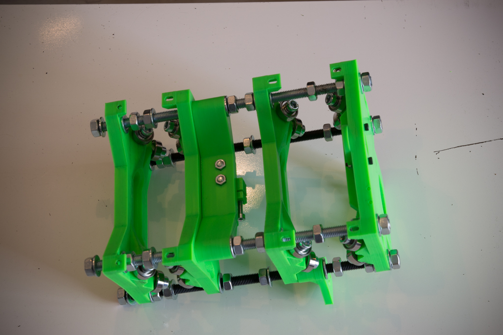
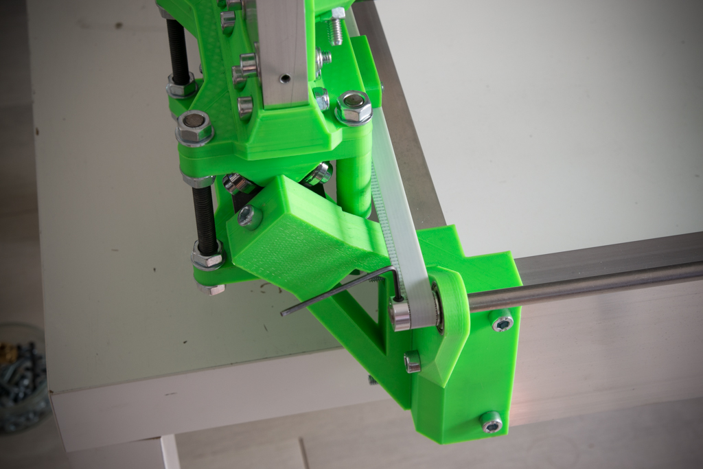
- Position the fasteners of the threaded rod M10 in contact with the printed corners and at the bottom of the box screed, drill and screw with sheet metal screws
- Position the threaded rod m10 in its supports
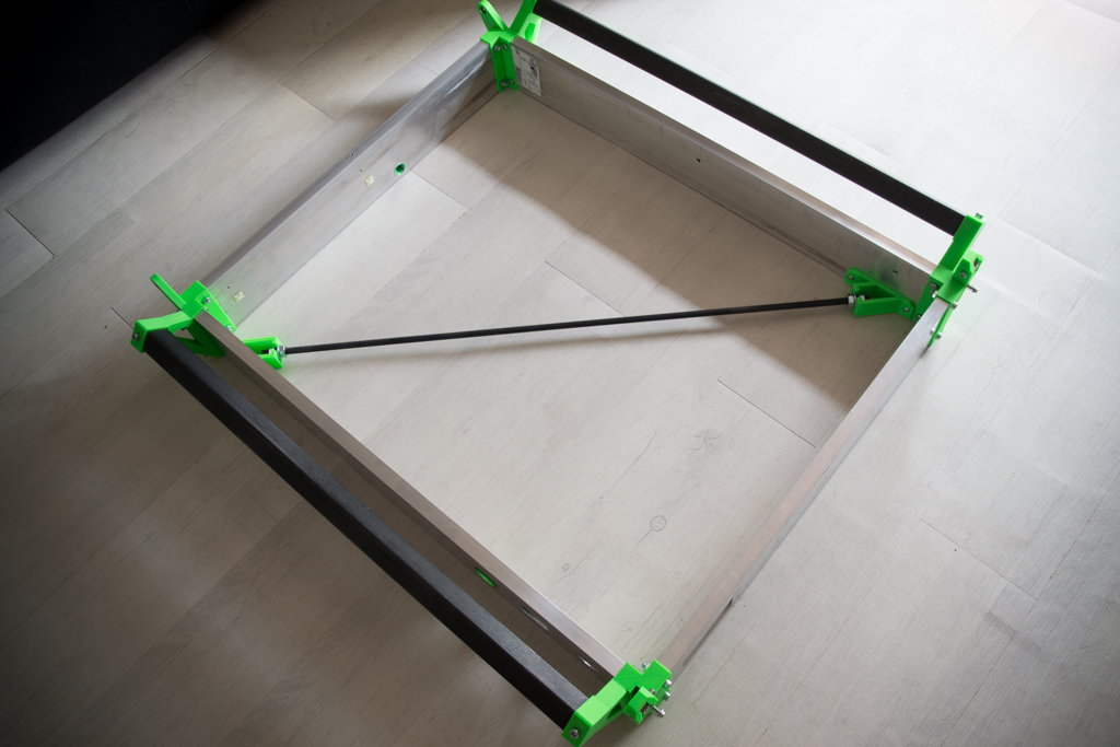
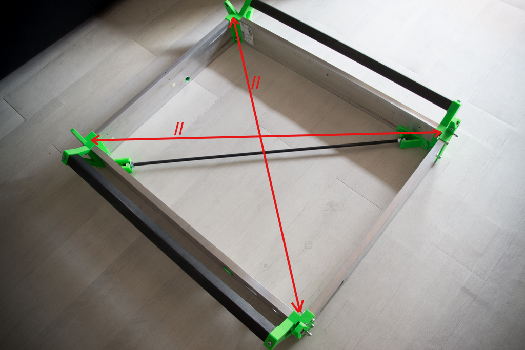
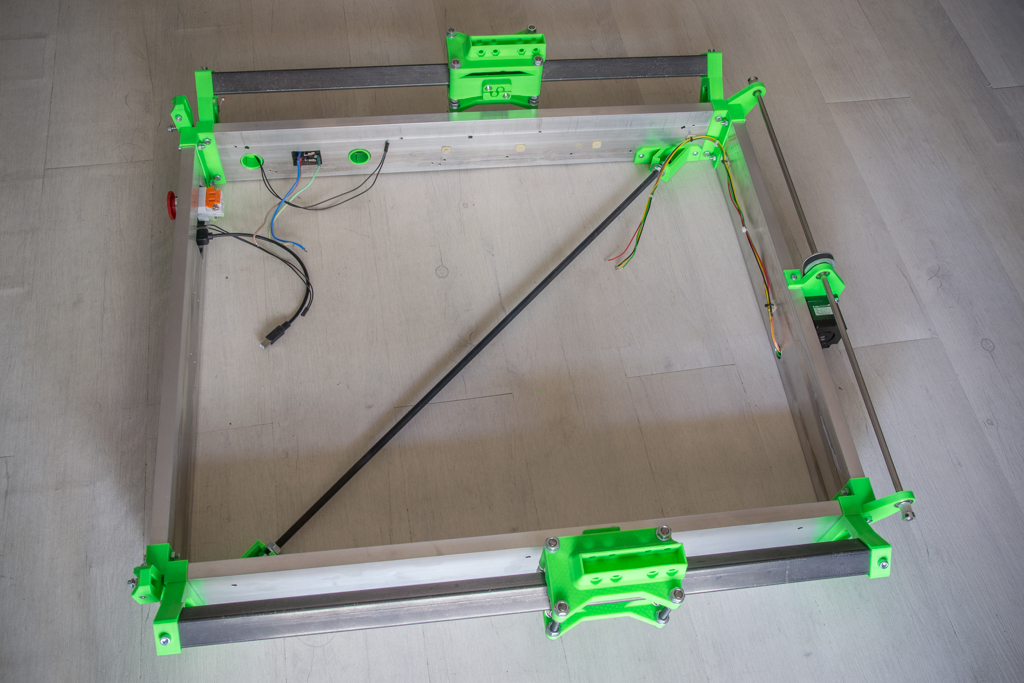
- Carefully adjust the perpendicularity of the assembly by having the same measurement on both diagonals then tighten the nuts of the threaded rod, then check that it has not moved while tightening.
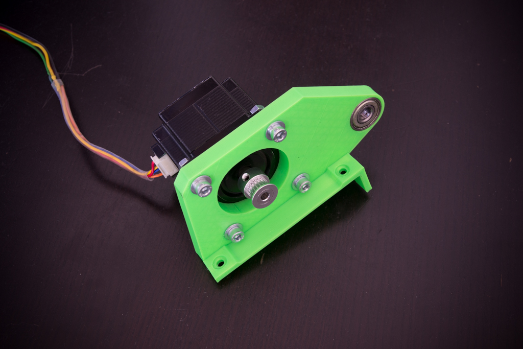
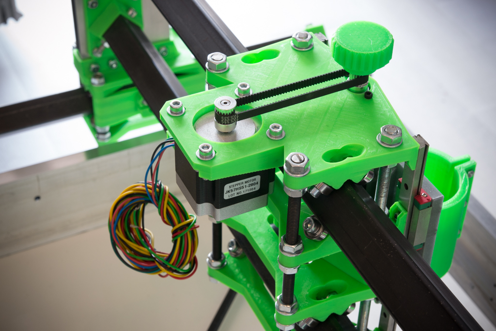
- Take the printed part of Y motor support , insert the bearing 608zz and screw the nema 23 (without tightening for the moment)
- Put the piece in the middle (we are not to the millimeter for this measure) then point the holes, drill and screw with sheet metal screws. (think of making a hole through the box screed to get the motor wires to the back of the motor)
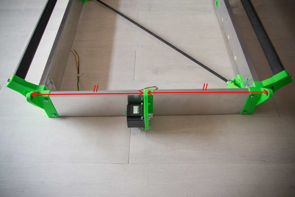
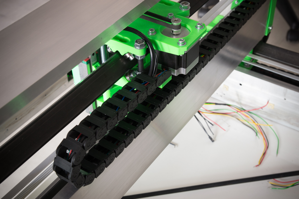
- Insert the smooth rod of 8x688mm by threading a washer, the pulley 60 teeth, the belt and then the pulleys 20 teeth at the ends as in the photo
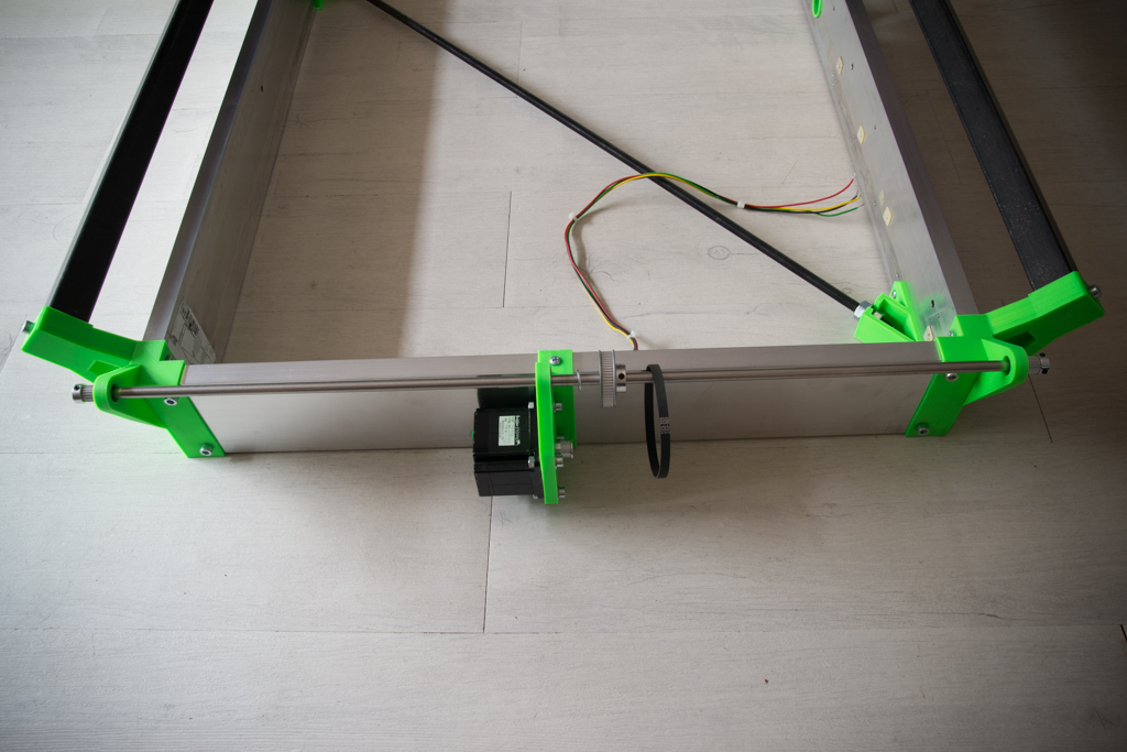
- Put everything in place and tighten
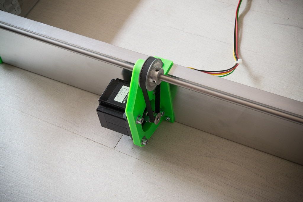
Plate making
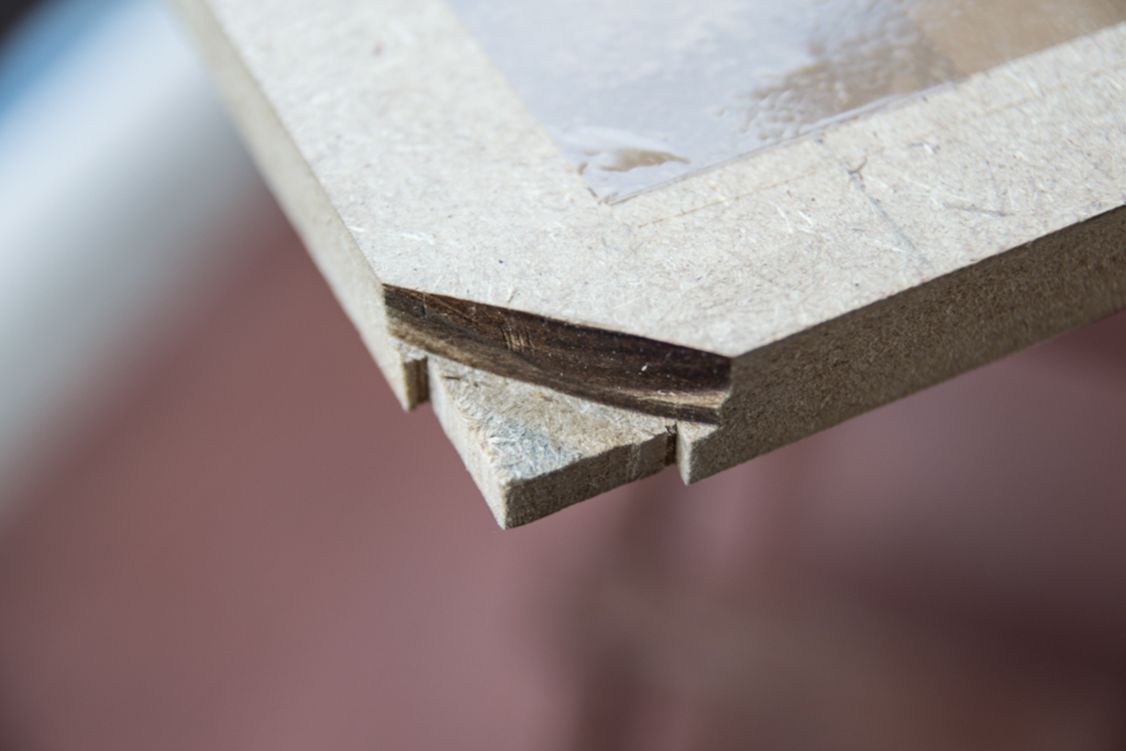
- Take your wooden tray and cut the 4 corners like this so that it fits

- Then remove the material below the corners to avoid being bothered by the screws below and that the tray can get to the box screed
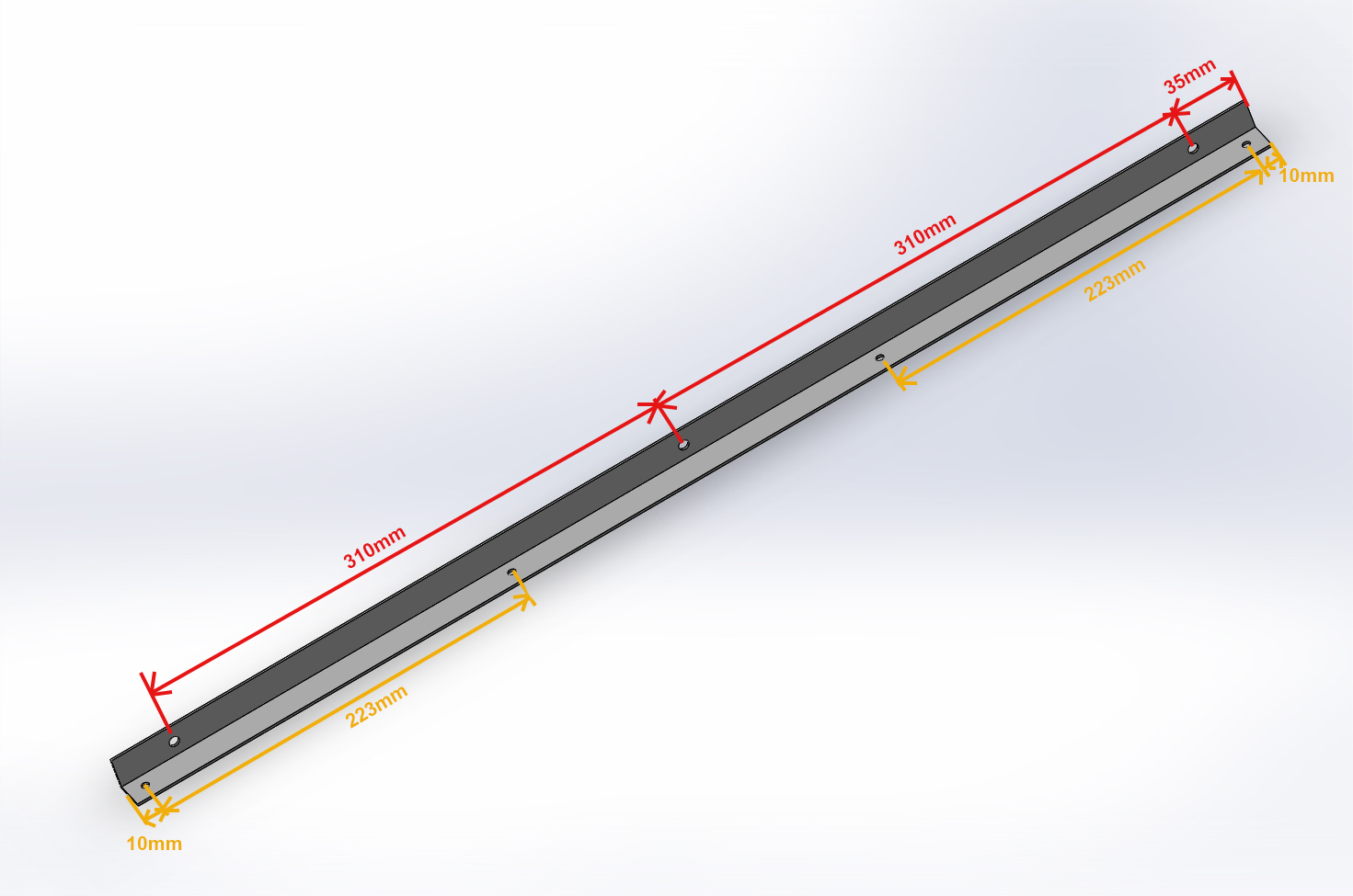
- Take the aluminum angles 20x20x690 and drill them like this:
- Holes measured in red are 10mm from the edge and drill at 6mm
- Holes measured in yellow are 10mm from the edge and pierce at 4.5mm
- Put on a flat surface 4 objects of the same thickness (here rolls of large tape) put the tray upside down, then put the frame of the RS-CNC upside down.
- Position the angles
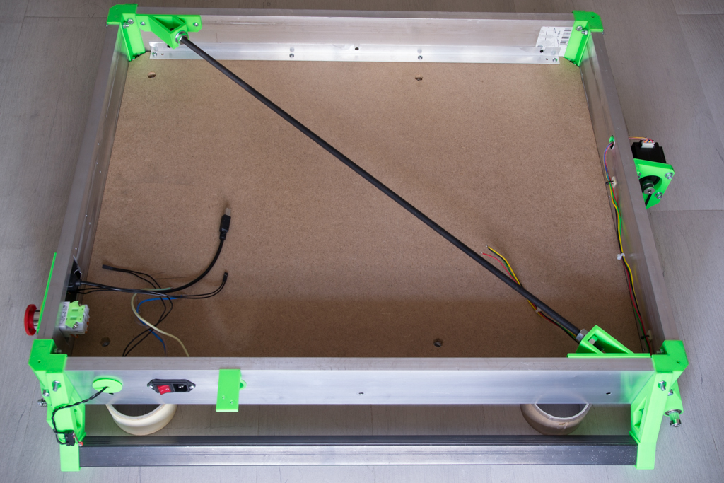
- Screw them first on the tray on the side of the 4 holes
- Then point the 3 holes on the box screed and drill to 6mm

- Open the 3 holes of each angle by cutting the red lines on the pic:

- Trace the clamps fixing holes on the plate
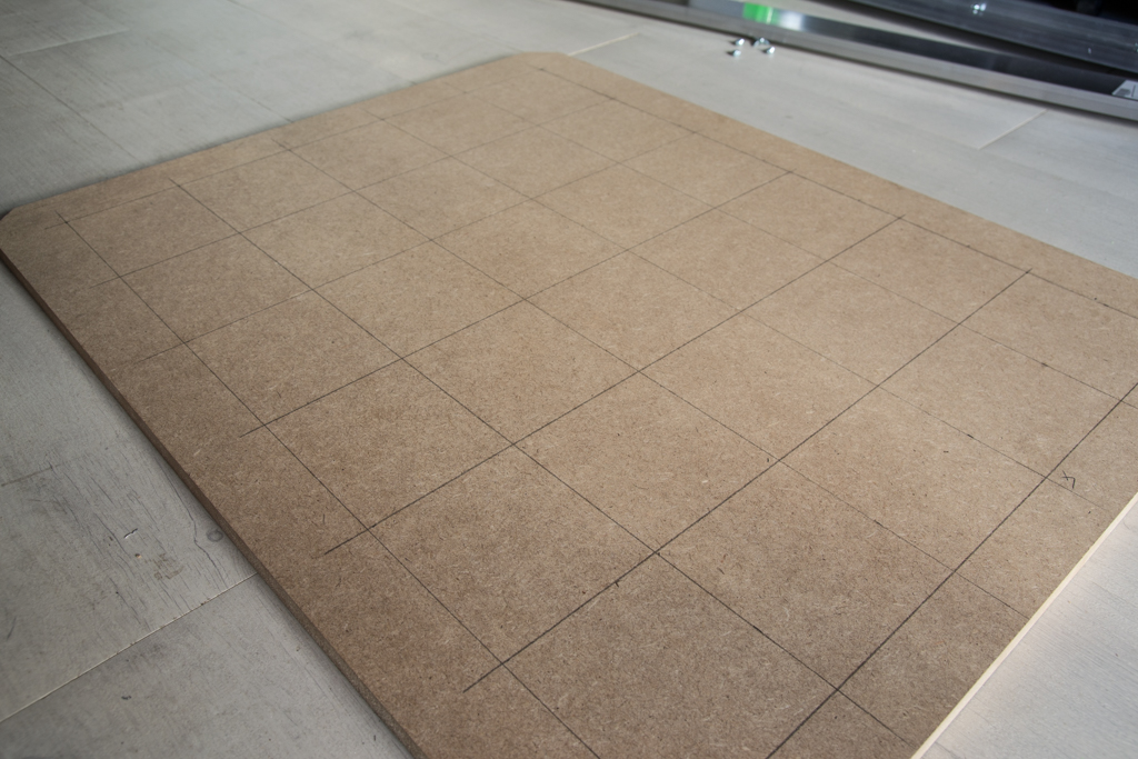
- Drill everything at 9mm
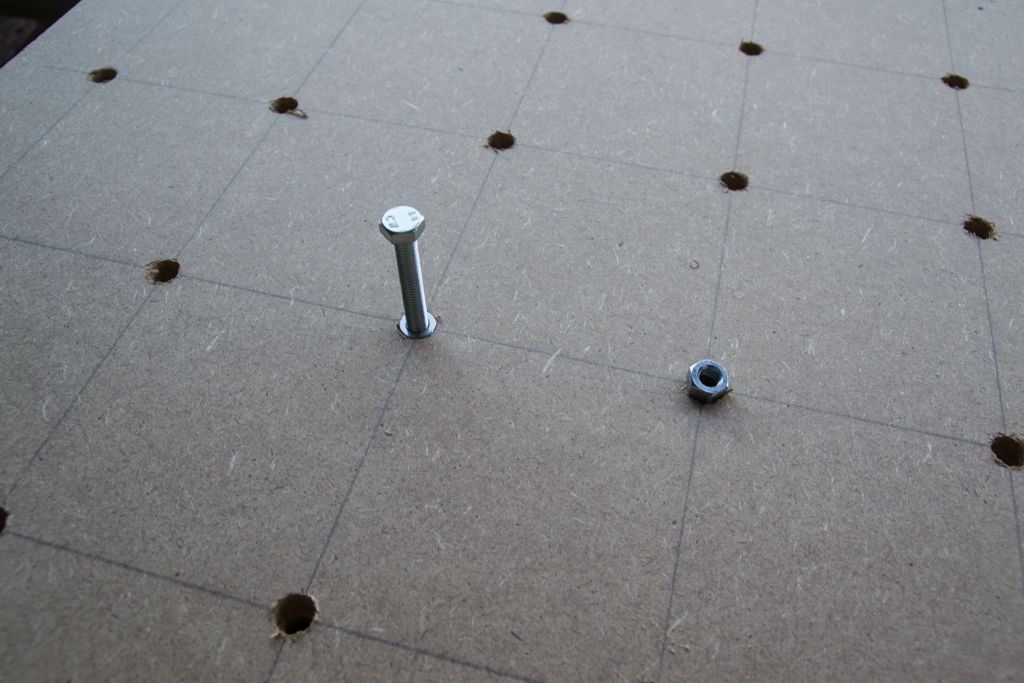
- Then from below, drill at 13mm only on 10mm depth
- Hammer an M8 nut into each hole (If you have neighbors, do it at a correct time so they do not hate you 😀 )
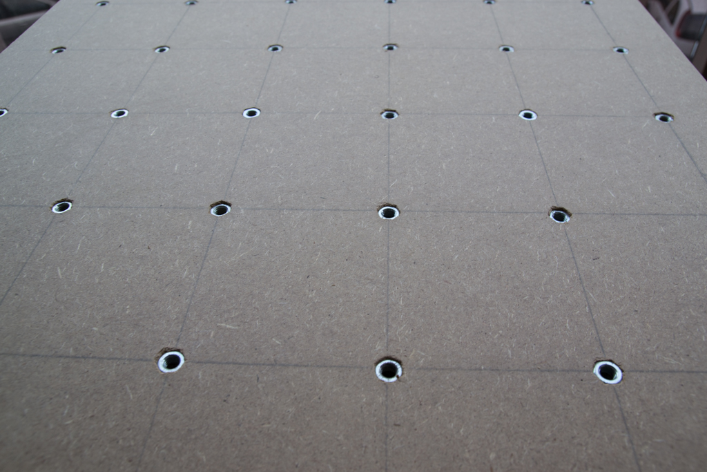
- Put large tape on top of each nut to prevent dust from passing through
- You can screw reinforcement angles under the tray if you wish
- Paint the top of the plate
- Put it aside for the moment
Back to our frame
- Screw the bearing 606zz on the 4 “Dollybase”
- And we start assembling like this
- We finished up on the rails in this direction (check the picture!)
- For tightening, it is necessary to tighten neither too much nor not enough, it is necessary that each bearing is in contact, without that it creates big hard points, it must circulate by hand resisting a little but not too much

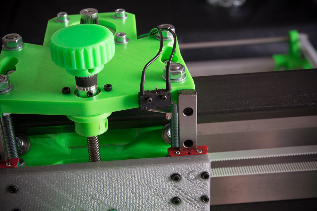
- Cut out and drill the box screed from the front face like this (the 4 holes and the left cutout are made for the front panel plate, the 4 right holes for the TFT screen bracket, the holes for the plate buttons are not through because it is screwed with sheet metal screws, the TFT fixing holes are 3mm and through)
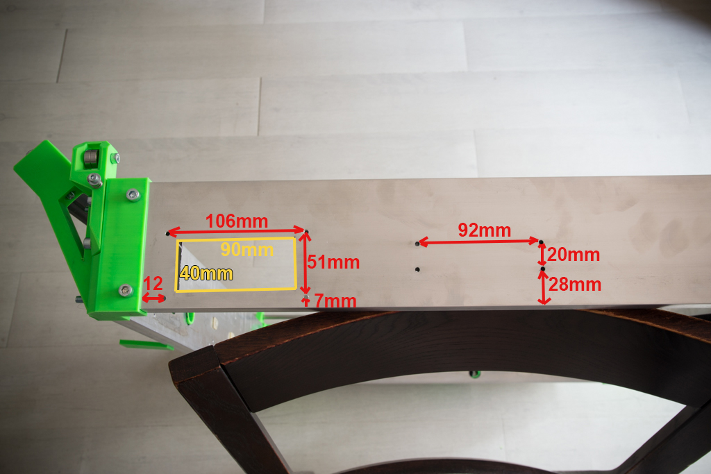
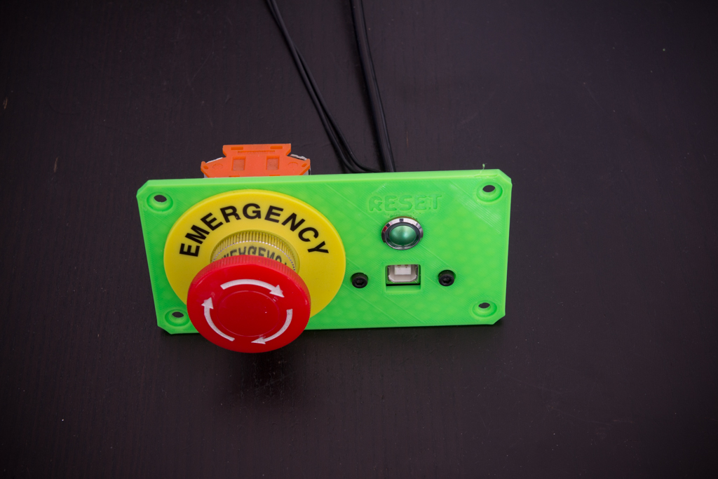
- Once done, you can assemble the button plate like this and screw it on the frame
- Now drill and cut like this the box screed on the left side of the machine (the 31mm hole on the right was plugged with a printed part because I recycled the box screed of my old R-CNC)
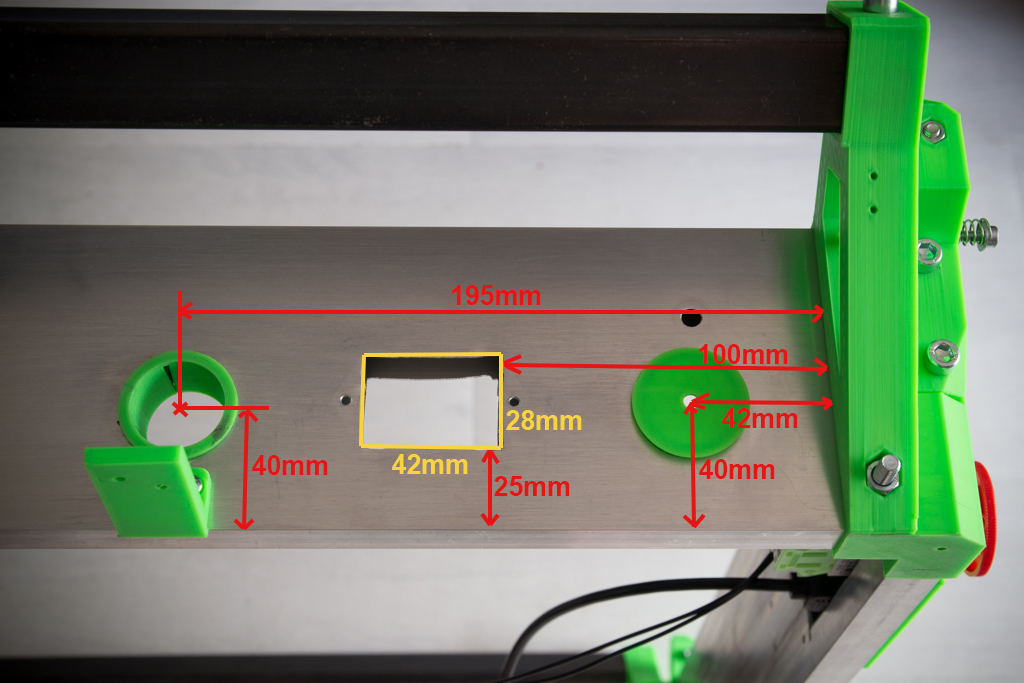
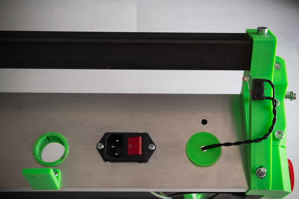
- Then screw on the plug / switch module and switch Y (to be wired in “normally closed” “NC”)
- Take the two box screed of 266mm and put them in place
- Set up the drilling model and report all the holes
- Do the same on both sides of the two box screed
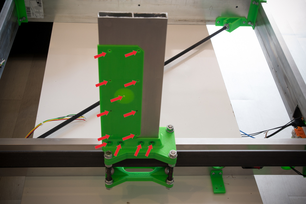
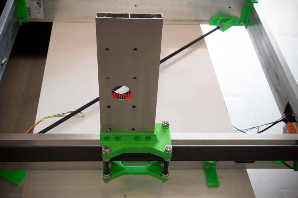
- Drill all the holes at 6mm except the big central hole at 30mm
- Screw the box screed to their base
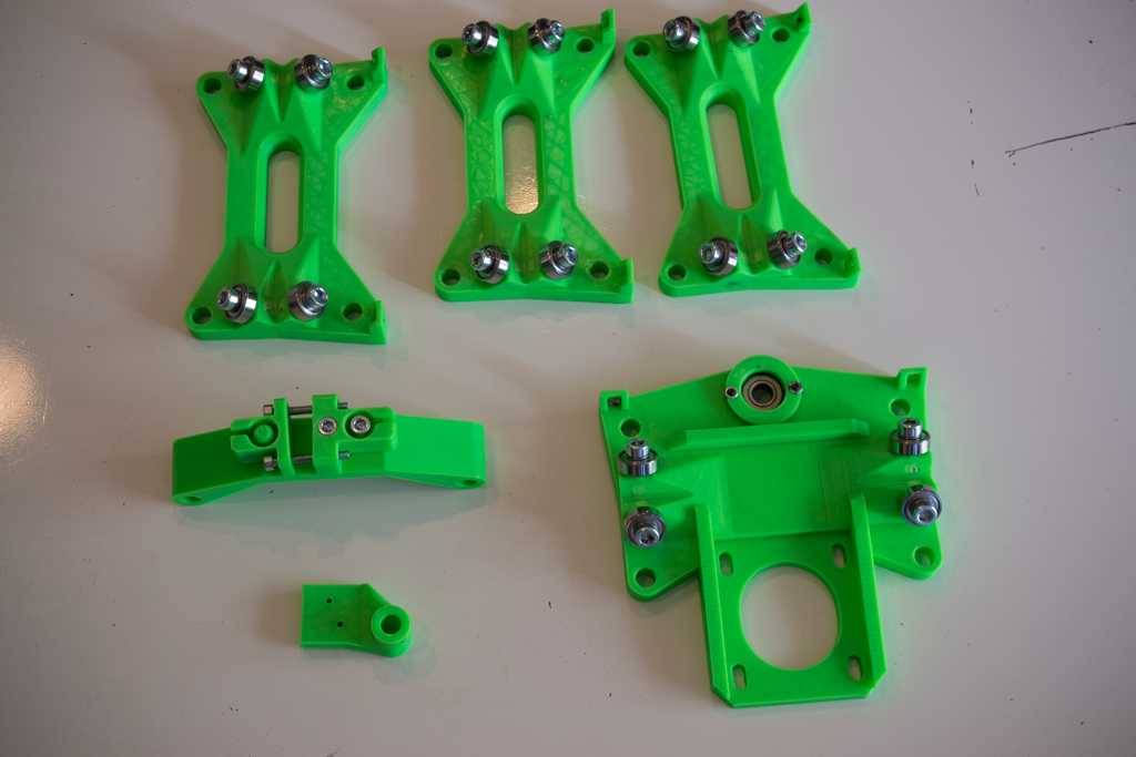
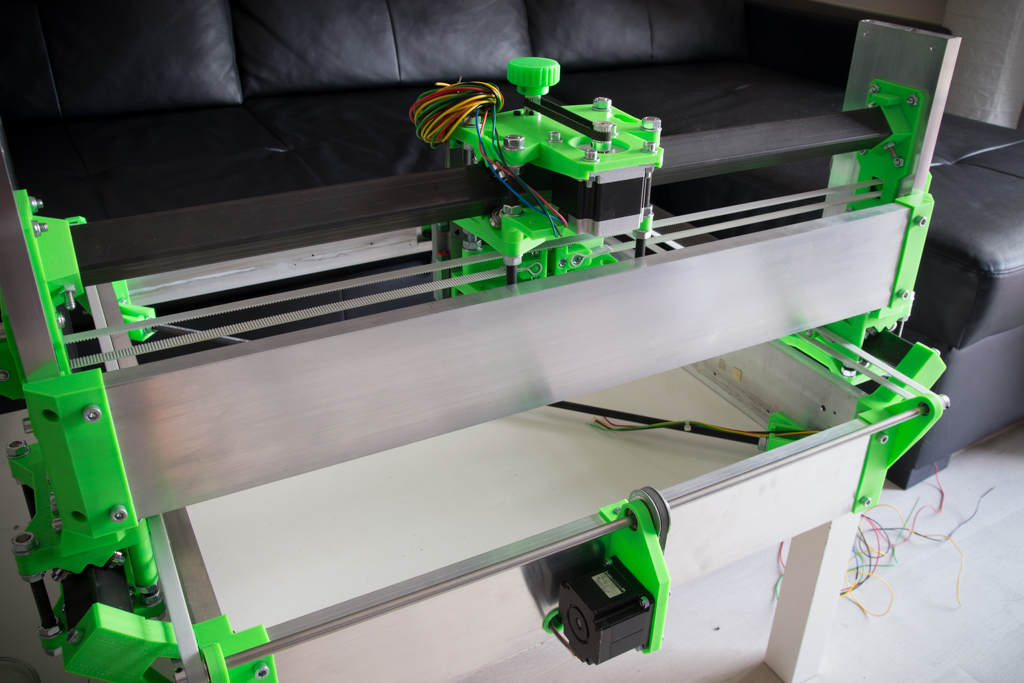
- Prepare the parts for the X / Z module
- Screw all 606zz bearings with M6x20 screws
- Insert the 608zz bearing on the dolly_top and screw in the locking piece.
- Screw the X strap fasteners
- Assemble the module like this:


- Take the square tubes, put them in their supports, postpone the holes and drill to 6.5mm
- Thread the X / Z module (nuts not tightened)
- Put the screws through the square tubes and tighten
- Do not tighten the X / Z module yet

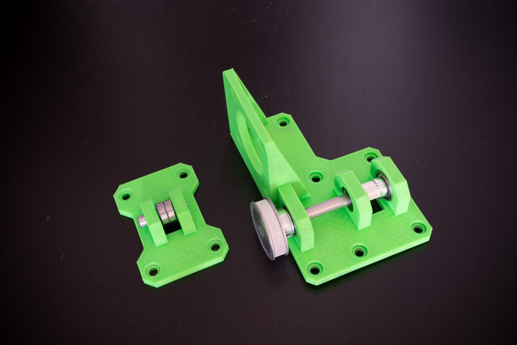
- Prepare the X belt parts as follows:
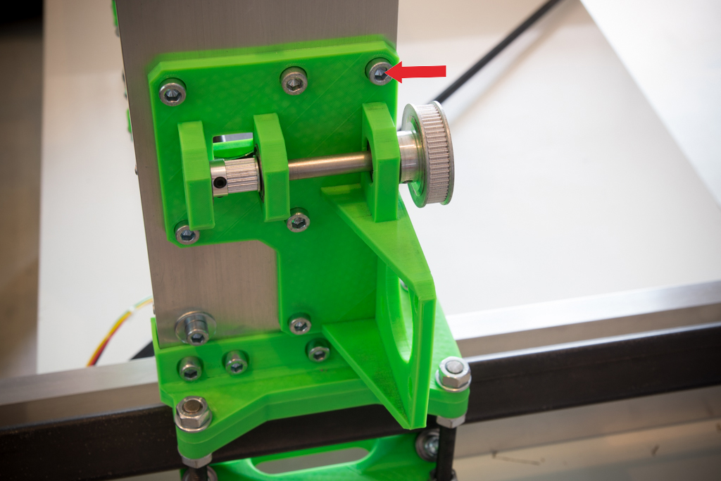
- Put the left piece in place
- Report the marked hole with the red arrow
- Drill the hole
- Fix the piece to the box screed
- Seen on the other side:

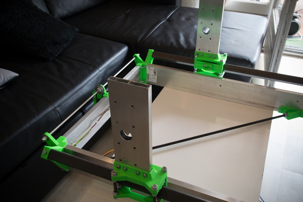
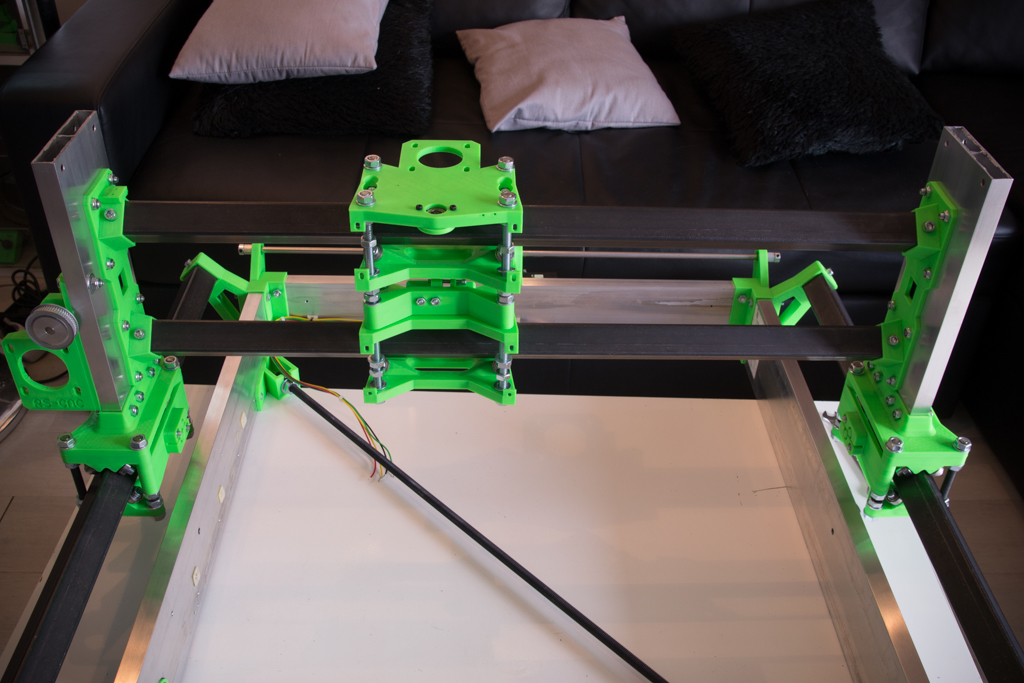
- Overview at this point
- Adjust and tighten the nuts of the X / Z module
- All bearings must be in contact with the square tube (put your finger on each bearing and move the carriage to see if the bearing is driven)
- Do not compress the square tube too hard otherwise it will cause hardness in the mechanical movement
- The pressure should not be too low either at the risk of having play
- The good pressure of the bearings is when you can move the module with a little resistance but not too much

- Fix the MGN12 rails of 200mm each
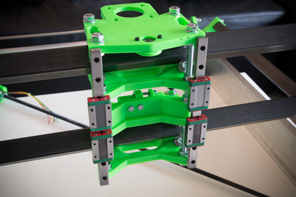
- Prepare the spindle support plate like this:

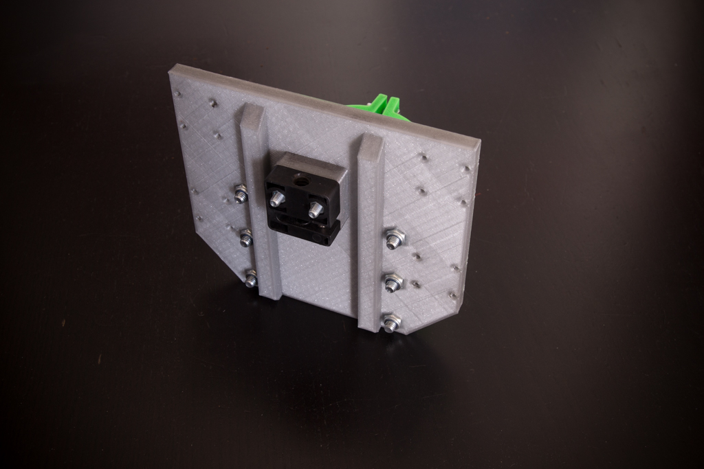
And fix the set to MGN12 bearings
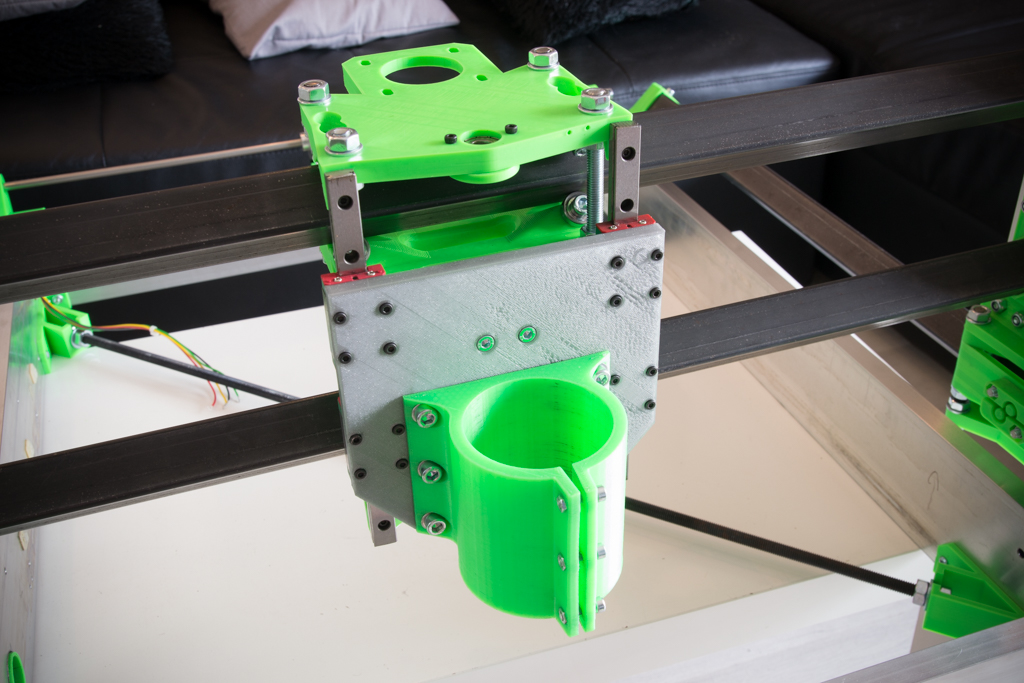
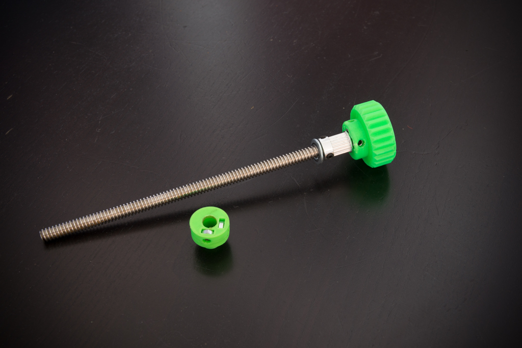
- Take the ACME rod dia 8mm at 2mm pitch
- Prepare it as in the picture
- Insert 2 M4 nuts into the Z locking piece and then two M4 grub screws
- Thread the rod from above
- Thread the Z locking piece
- Screw the ACME rod a little
- Put the 20-tooth pulley in abutment with the 608zz bearing at the top
- Hold the Z locking piece under the 608zz bearing and tighten it
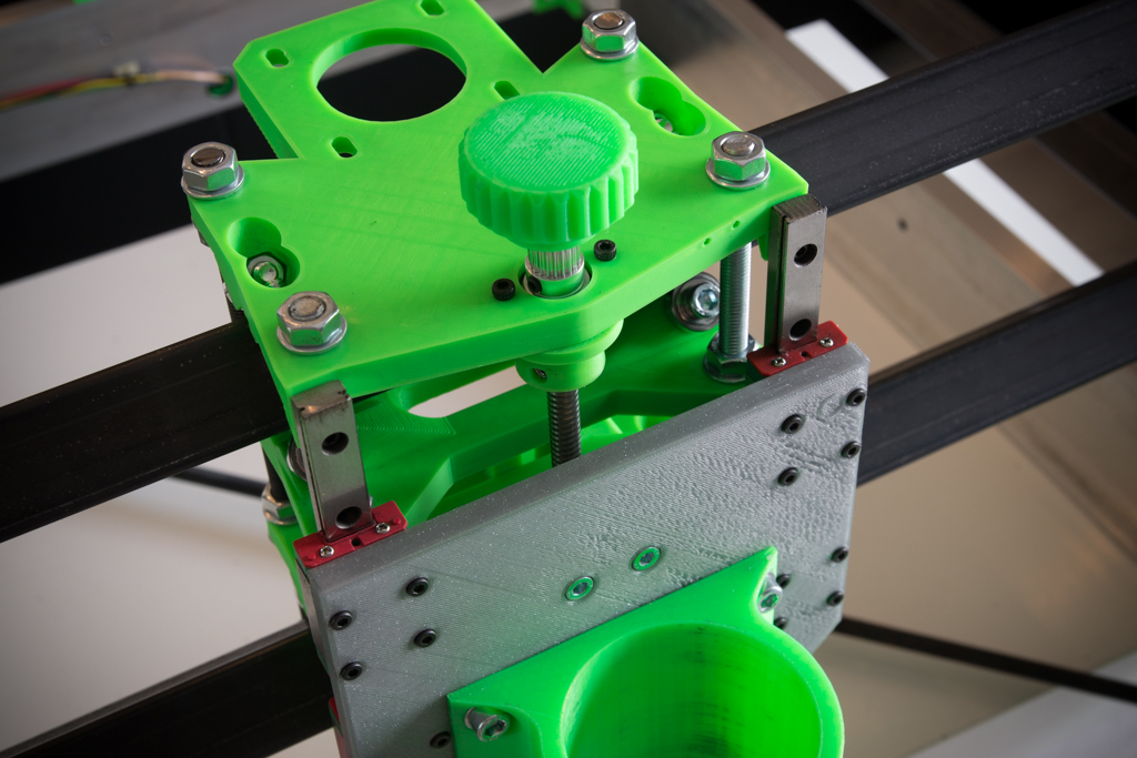
- Mount a Nema 23 in Z
- Fit the belt and tighten
- Tighten the motor screws
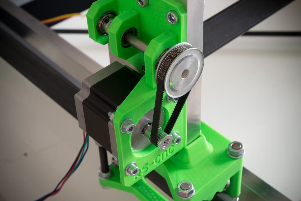
- Mount a Nema23 in X
- Fit the belt and tighten
- Tighten the motor screws
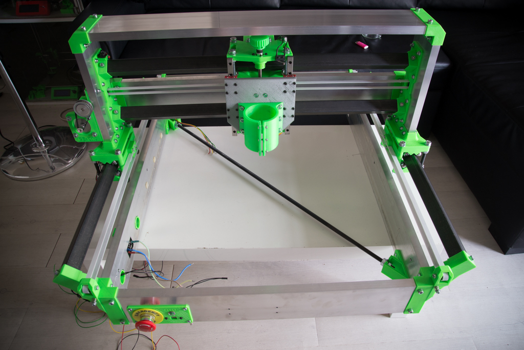
- Fit the 3 large belts of the machine and tension them using the tensioners
- untighten one of the 2 pulleys 20 teeth of Y
- Rear end the two Y-carriages
- Tighten the 20-tooth pulley that was released
- That’s it, your X axis is perpendicular to Y
- Wire the X and Z switches to “normally closed” (NC) (solder one wire to the NC terminal and the other to the COM terminal)
- Mount the X and Z switches on their location using M2x10 screws

- Fix the rear reinforcement using sheet metal screws
- Prepare the upper reinforcement with 24V leds ribbon
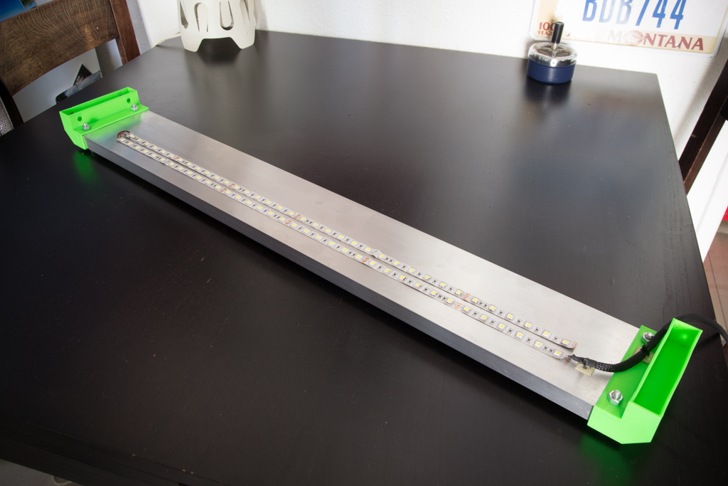
- Screw it
- Install the spindle
- Pass the cables through the X dragchain
- Fix the dragchain
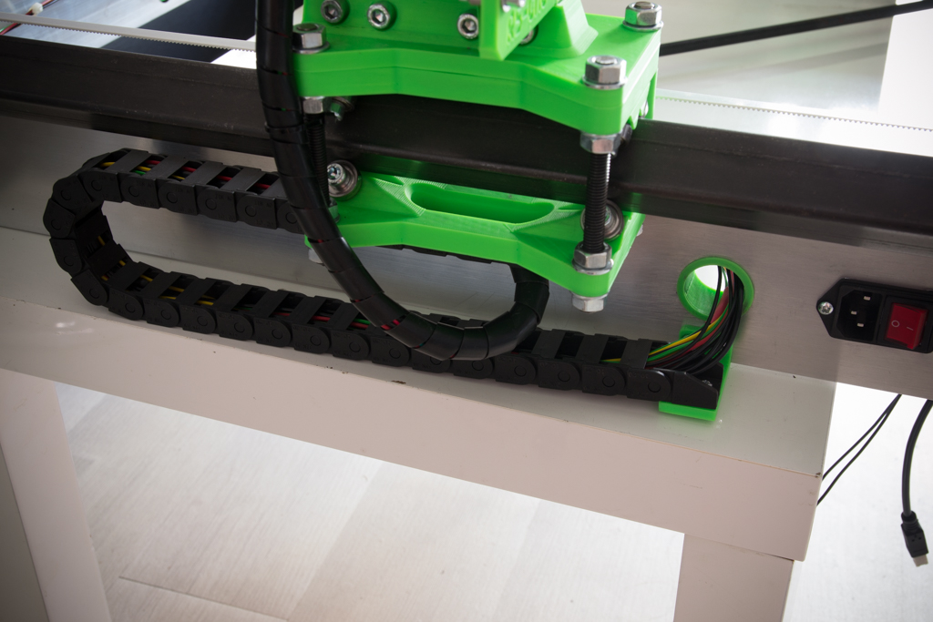
- Pass the cables through the Y dragchain
- Fix the dragchain (There are no pre-holes under the Y dolly_base, you have to make two holes of 2mm yourself)
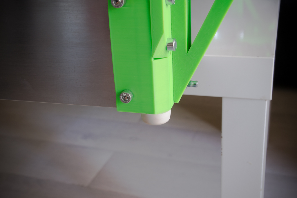
- Screw the rubber feet to each corner
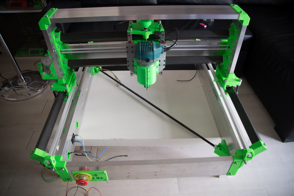
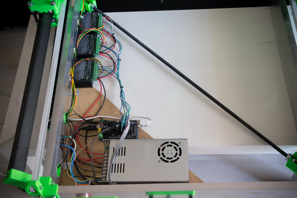
- Example of layout of the electronics, but do as you want !
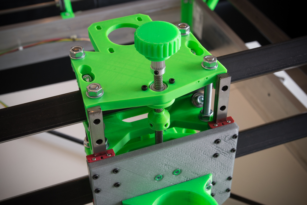
- Put the 6 tray knobs in place
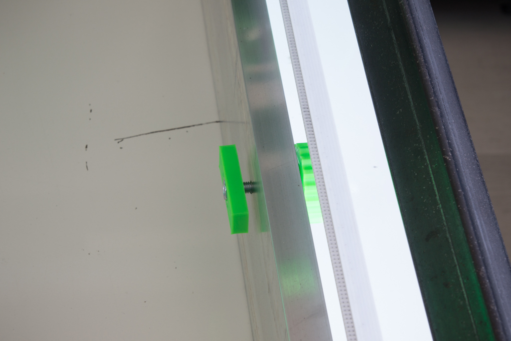
- Put the tray, adjust the height of the 4 corners and tighten the knobs
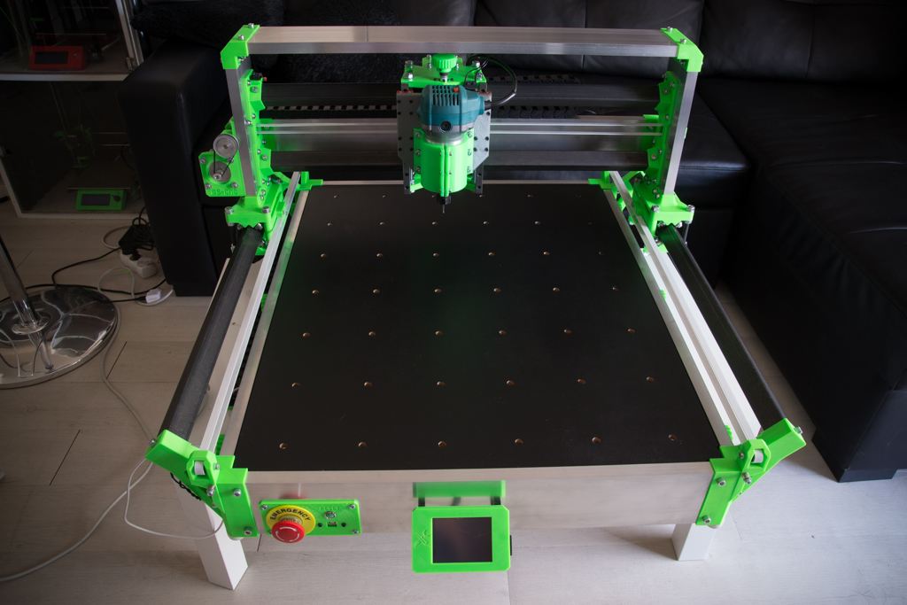
The assembly tutorial is finished, it’s time to move to the wiring
Wonderfull project! Thank you for sharing!
May I ask at which lengths you cut the threaded rods?
Kind regards,
Pascal
Your’e welcome Pascal,
All you need is written on the tutorial https://www.makerfr.com/en/cnc/rs-cnc/liste-des-pieces-rs-cnc/
Cheers
Romain
Hi,
are you using an aluminium zplate? It seem very expensive to have built one. Online CNC service quote minimum 130 euros for it.
Do you think it is mandatory or the printed part will be enough?
thx
Hi Andrea !
I’m using the printed Z-plate in PLA without problem !
Hello,
Il semble y avoir une erreur dans la 1ère partie du tuto, ou une erreur dans la liste des achats de quincaillerie.
ll est indiqué d’utiliser les 2 vis M4x40 pour fixer les roulements sur les tendeurs de courroies.
Mais il n’est pas indiqué de se procurer des vis de M4x40.
J’imagine que c’est les M4x30 ?
Bonne journée.
Hello !
De tête il me semble que pour les roulements des tendeurs de courroies Y, il faut des 5×30
Oui effectivement, je confirme c’est bien du 5×30, peut-être le modifier dans le tuto ?
Bonne soirée.
Il n’y a pas d’erreur dans le tuto, mais apparemment c’est ambiguë, les vis 5×30 sont pour les axes des roulements, les vis 4×40 sont pour les vis de tension (là où on voit le ressort)
Hello,
I like your prject very much than you for makeing it available 🙂
I have a couple of questions:
1) how many rolls of green PLA I should buy – 2 kg will be enough?
2) I am OK with mechanical works and connectiing wires, but I am not really good at electronics – will I be able to make this project this way?
3) my new 3D printer will be here next week, it has 260 mm diameter bed and 370 mm working height – height will be no problem I guess, but will the diameter be enough?
4) I ordered this router: https://www.aliexpress.com/item/220V-800w-30000r-min-Collet-6-35mm-AU-Plug-Corded-Electric-Hand-Trimmer-Wood-Laminator-Router/32891159761.html?spm=a2g0s.13010208.99999999.260.1f703c00c3pS2a
It will cost USD 32.18 on 11/11 sale. But did not find the body diemeter – is it 65 mm and no need to change the 3D part?
5) I found that this variable speed router also will be quite good deal on 11/11: https://www.aliexpress.com/item/Spindle-Motor-500W-ER11-chuck-CNC-52mm-clamps-Power-Supply-speed-governor-For-DIY-CNC/32731132405.html?spm=a2g0s.13010208.99999999.266.1f703c00c3pS2a
It will cost USD 78.10 (15 USD savings :-)) I have no idea which would be better, so would you pls advice – I have time to cancel one of those orders before 11/11 🙂
Thank you very much for your time to answer my questions.
Kind regards, Attila
PS: my son lives in Paris, so maybe it is easier and cheaper to deliver the shield to him. He will come home to Christmas, so can bring it with him. Pls advice and I will place the order at your boutique accordingly.
Hi Modisa,
1- you need 2kg of PLA
2- All Electronic is simplified, even the diagram, look the tutorail
3- All parts are designed to be printed with 200*200mm 3D printer, your printer is enough !
4- this router is 65mm, it’s good
Shipping costs for the shield are 3.50€ for France and only 5.60€ for the rest of the world !
Cheers
Romain
Hello Romain,
Thanks for the prompt reply!
I will buy 2 kg PLA and start printing as soon as I finish testing my new printer – according to the post tracking info it will arrive on Monday 🙂
About router – is it better to have a fixed rotation one with 800W power, or a variable rotaion one but just 500W? Because the USD 15 discount is very promising if a variable rotaion one is a better choice (e.g. less rotation for organic glass, etc)
And Electronics – I examined the power scheme and the command scheme also, but did not find the Arduino and the TFT display. It must be obvious for an expert 🙂 but I am not familiar with those, so I would really appreciate if you could add one more scheme, where those are also shown.
Thanks fo your care 🙂
Cheers, Attila
PS: as I see my budget, I will place the order for the shield just a bit later… first I have to cover the mechanical assembly 🙂 I am just in love with this project…
It’s better to have a speed variator
The arduino is plugged under the shield, and TFT is plugged on its plug on the shield, no more wiring, no diagram needed !
Romain
Thank you, for now I am OK.
Now I have to start the hard work 🙂
Hoping that I will have bother you as less as possible, Attila
Salut, certaines tailles de vis à utiliser ne sont pas mentionner comme par exemple pour fixer la partie tendeur et la partie roulement aux 4 coins, que faut-il utiliser stp ? 🙂
Bonne journée !
Bonjour Romain,
Tu indique qu’il faut percer le gros trou central à 30mm. C’est peut être une question bête, mais tu le perces avec quoi comme outil ?
Merci
Thierry
Bonjour Thierry,
On réalise ce trou à l’aide d’une scie cloche, autrement il est possible de faire un carré à la scie sauteuse, le but étant de faire passer la courroie à travers.
Bonne journée
Romain
Hi congratulations for the project,
very nice work.
I am going to build it. But I have a question : I see some holes on the aluminium 100×20 profile, do you have a template to do it ?
thank you
Hi Domenico,
All is explained on this page, which step do you not understand ?
Quel travail incroyable, et quelle grande générosité de mettre en open source ! Merci!
En soit , quel est la capacité du router?
Bonjour Nova,
Merci pour les encouragements 🙂
Que veux tu savoir exactement sur le routeur ?
Hi,
First of all great project! Congratulations. Just a quick question that I wanted to ask. Where can I find at the assembly which screw to use at each step? I just don’t want to make any mistake. Or should I just try to fit any screw according to the length of the part?
Best Regards,
Andreas
Hi Andreas,
You have to try to fit any screw according to the lenght of the part because if i would put all screws details, tutorial will be 2 times longer !
Have a good day
Romain
Hello, super CNCmais à quoi servent les endstops ? Je croyais qu’ils n’étaient pas nécessaires, est-ce une protection ?
Bonjour Guillaume,
Ils ne sont pas nécessaires, mais servent à faire un homing pour ceux qui le veulent et servent aussi de sécurité.
Romain
Hello.
What is the Brand of pla you are using? The green colour looks amazing.
Hi Christopher,
I’m using a french brand named “Arianeplast” , the color is “Fluo Green” wich you can find on other brand
Romain