[provisional tutorial] mount a laser module

Avatar du membre
RoMaker
Administrateur du site
Messages : 5201
Enregistré le : 02 janv. 2017 20:24
Localisation : Montpellier
Contact :

[provisional tutorial] mount a laser module

Message par RoMaker »

Hello !
I specify that this type of diode laser can cut only thin layers of plywood, balsa, cork, paper, cardboard ... It is essentially made for engraving, even for the most powerful diode models.
If you want a real laser cutter, you have to invest in a CO2 laser!

The use of a laser is very dangerous, you must take all measures to protect your eyes using glasses adapted to the type of laser used and be alone in the room where the laser is running.
Depending on the materials in contact with the laser there may be very toxic fumes, avoid burning on PVC, ABS or other plastics without prior information. The room must be ventilated in all cases.
As you know, the laser burns the material, so there is a risk of fire during the job, do not leave the machine unattended.
Do not try to engrave reflective materials that could deflect the laser anywhere, and anyway it would not engrave on it!


Hardware:

A laser module ! This one is a very good quality / price / performance ratio: http://s.click.aliexpress.com/e/drcHwQey
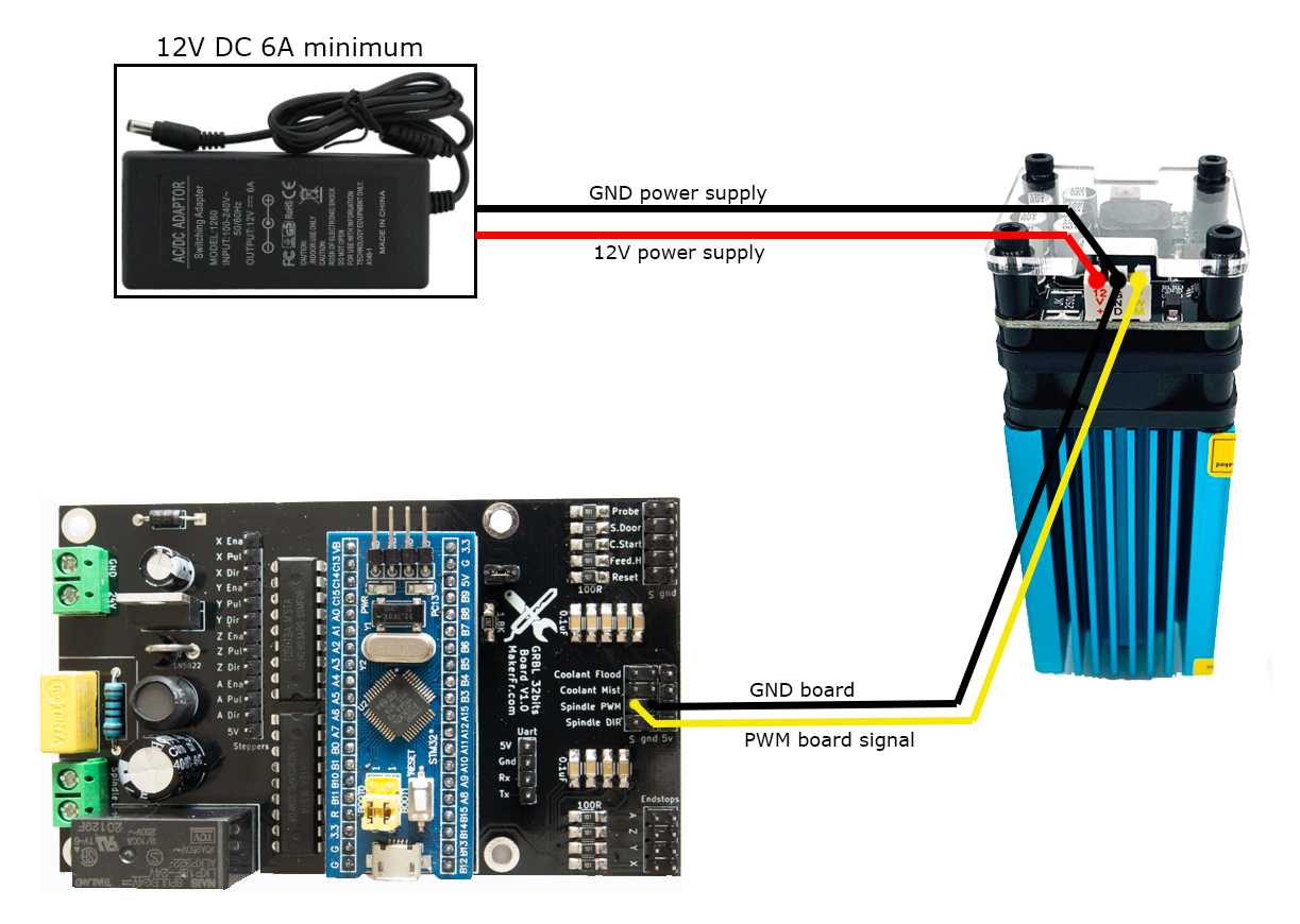
A power supply, 6A minimum : http://s.click.aliexpress.com/e/reLsGvqg
A printable mounting bracket (thanks to Vair327 ): https://www.thingiverse.com/thing:4012864

Wiring diagram:
Image

The new firmware modified by MStrens:

Modifications: Signal inversion option developed by Mstrens enabled, Laser mode enabled.

Firmware for custom version: https://www.makerfr.com/wp-content/uplo ... 150120.zip
Firmware for easy way : https://www.makerfr.com/wp-content/uplo ... 20-HEX.zip

Note that once uploaded, you will need to run the $RST=$ command to clear old cache data, be careful if you made any custom changes other than the original ones they will be deleted.

Adjust the focal length:
(coming soon)

First test:
(coming soon)
Turn off the switch of the spindle
laser soft commands:
Laser will be turned on by M4 command (M4 S*** -> *** is a number between 1 and 255, 255 is full power)
Laser will be turned off by M5 command

Power switch, on the laser module: You must first turn on the RS-CNC32 before turning on the laser module, and first turn off the laser module before turning off the RS-CNC32, in short, do not turn on the power of the laser with the RS-CNC32 turned off otherwise the laser lights up full power !
vair327
Messages : 36
Enregistré le : 10 févr. 2019 22:22

Re: [provisional tutorial] mount a laser module

Message par vair327 »

RoMaker

Has this HEX file been verified to work? I tried loading it on a spare stm32, and I do not get any comm with the esp. I thought maybe it was the new board nope working board does the same thing with this new HEX loaded. I get ?? in the display top right.
Avatar du membre
RoMaker
Administrateur du site
Messages : 5201
Enregistré le : 02 janv. 2017 20:24
Localisation : Montpellier
Contact :

Re: [provisional tutorial] mount a laser module

Message par RoMaker »

Hi,
I didn't try the .hex file because i used the custom way, i'll verify that and let you know...
Avatar du membre
RoMaker
Administrateur du site
Messages : 5201
Enregistré le : 02 janv. 2017 20:24
Localisation : Montpellier
Contact :

Re: [provisional tutorial] mount a laser module

Message par RoMaker »

vair327
Messages : 36
Enregistré le : 10 févr. 2019 22:22

Re: [provisional tutorial] mount a laser module

Message par vair327 »

That works!

Thanks
Avatar du membre
RoMaker
Administrateur du site
Messages : 5201
Enregistré le : 02 janv. 2017 20:24
Localisation : Montpellier
Contact :

Re: [provisional tutorial] mount a laser module

Message par RoMaker »

Cool :) the link of the first post has been modified ;)
vair327
Messages : 36
Enregistré le : 10 févr. 2019 22:22

Re: [provisional tutorial] mount a laser module

Message par vair327 »

RoMaker

I believe you missed adding the pull up resistor in the diagram you posted.

Sent from my Pixel 3 XL using Tapatalk

Avatar du membre
RoMaker
Administrateur du site
Messages : 5201
Enregistré le : 02 janv. 2017 20:24
Localisation : Montpellier
Contact :

Re: [provisional tutorial] mount a laser module

Message par RoMaker »

Hi Vair,
why do you say that ?
You don't need a pullup resistor because the PWM signal comes from the ULN2803, not directly by the chip !
vair327
Messages : 36
Enregistré le : 10 févr. 2019 22:22

Re: [provisional tutorial] mount a laser module

Message par vair327 »

RoMaker

In my testing I found the voltage from uln2803 was only 3.56 volts. I added a pull up of 2.2k which gave me a 5 volt pwm signal. I did not try to operate the laser diode directly from the uln2893 because in my searching could only find specs referring to 5 volt pwm for a control signal.

If it works without the pull up even better.

Sent from my Pixel 3 XL using Tapatalk

mstrens
Messages : 2611
Enregistré le : 27 févr. 2018 12:58

Re: [provisional tutorial] mount a laser module

Message par mstrens »

If it is a TTL input (on laser side), there is no need of a pull up resistor.
The current (and so the voltage) is driven by the TTL input (laser).
3.5 V is recognised as a level High.
It is normal that it is not 5 V because a TTL input has some transistors that create a voltage drop.

Anyway, adding a pull up resistor to 5V is not an issue just that it is not required.
Répondre