Drivers settings
The drivers must be adjusted for our machine thanks to the small levers on the side, I will not give you the exact combination for your config because it depends on the type of driver, and even the manufacturer, as well as the amperage of your motors, so we will learn to use the table printed on the hull where there are 2 or 3 categories:
- Motor amperage: Must be set according to the amperage indicated on the motor data sheet.
- Half current: Not found on all drivers, it is used to divide the current by 2 when the motor is stopped.
- The number of pulses needed to make a revolution. (On a 1.8 ° stepper motor)
In my example, I have a 2.8A motor, and I want to set my driver in 1/4 step (800 pulse/rev), and as here the option is present, I want to divide the current by 2 when my engines are stopped, here are the lines that interest us:
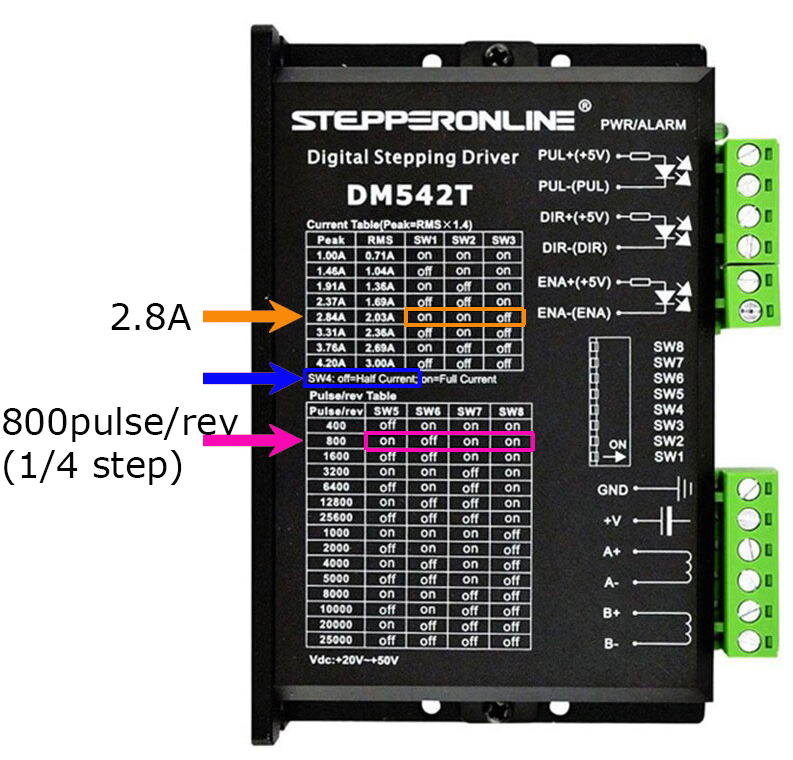
So that gives us for our example, an adjustment to be transferred to the levers like this:
![]()
If you have an RS-CNC32, its drivers must be set in 1/4 step (800pulse / rev)
RS-CNC32 wiring or any other 3-axis CNC + 4th axis possibility (XYZA)
Power wiring (click on the image to enlarge)
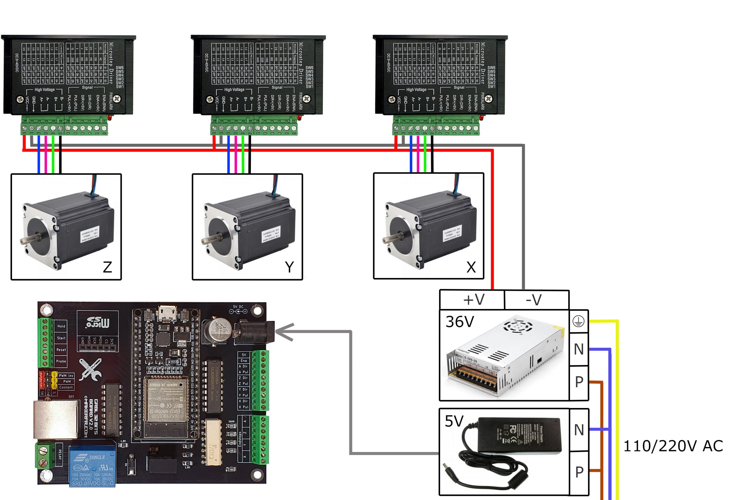
Info: The color of the stepper motor cables may vary from one manufacturer to another, do not rely on the colors in the diagram but on the manual that was delivered to you with your motors.
Control wiring

Info: You can also add push buttons (normally open) on the Reset, Hold, Start terminals
3 axis CNC wiring with 2 Y motors (XYYZ)
Power wiring (click on the image to enlarge)

Info: The color of the stepper motor cables may vary from one manufacturer to another, do not rely on the colors in the diagram but on the manual that was delivered to you with your motors.
Control wiring (drivers)

Control wiring (switches)
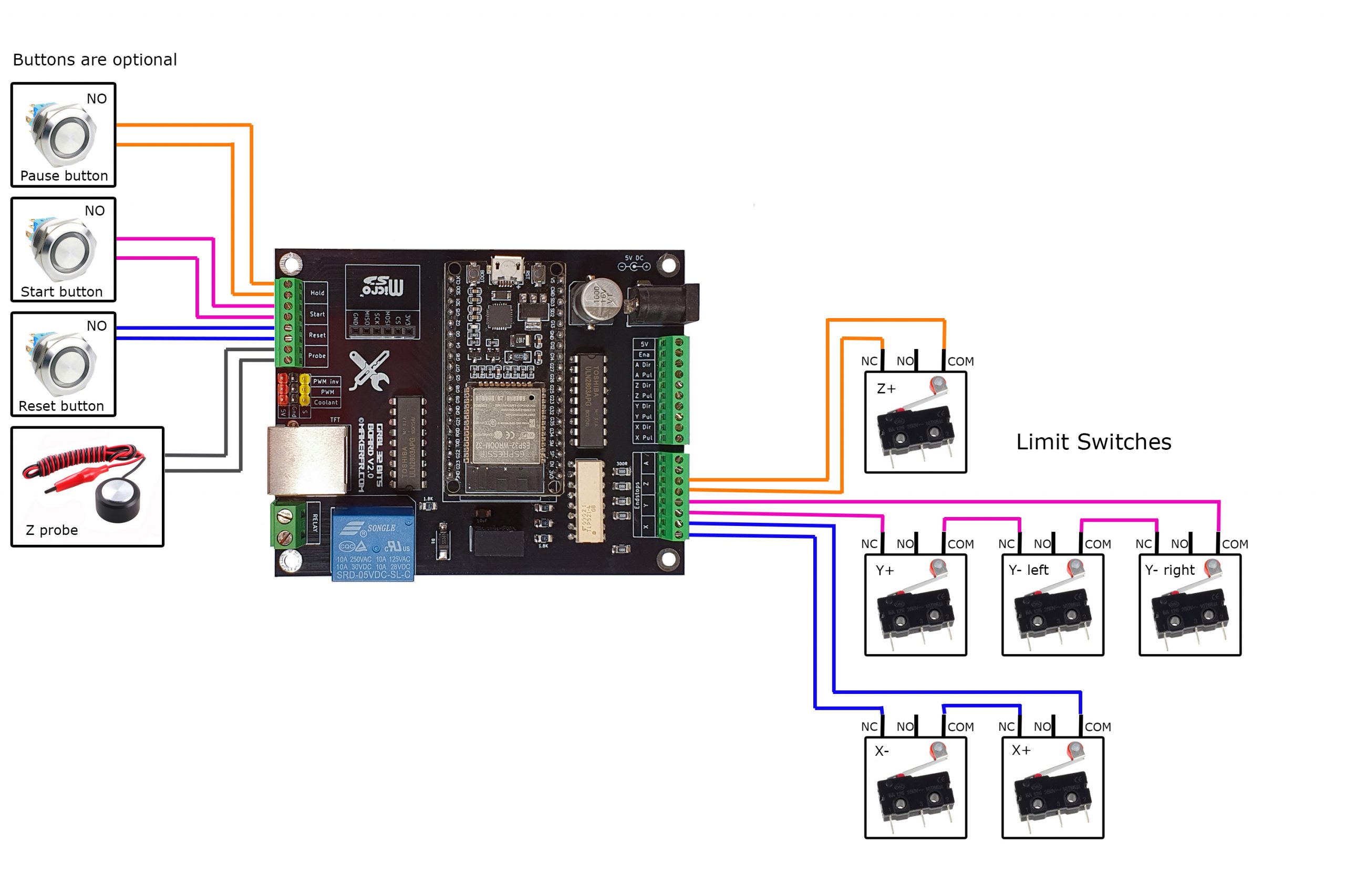
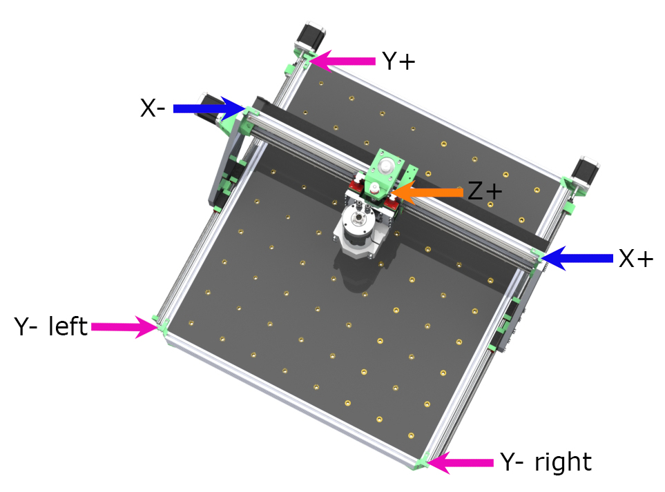
- The limit switches are wired in “normally closed”, in series (if you want to do tests without the limit switches, you must bypass the endstop terminals X, Y, Z)
- The control buttons (optional) must be in “normally open” and “momentary reset” type (which return when released)
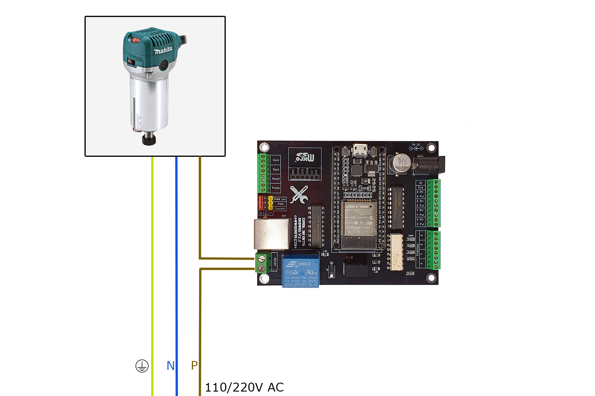
Simple router wiring, 110/220VAC single phase (Katsu, Makita, Dewalt, …)
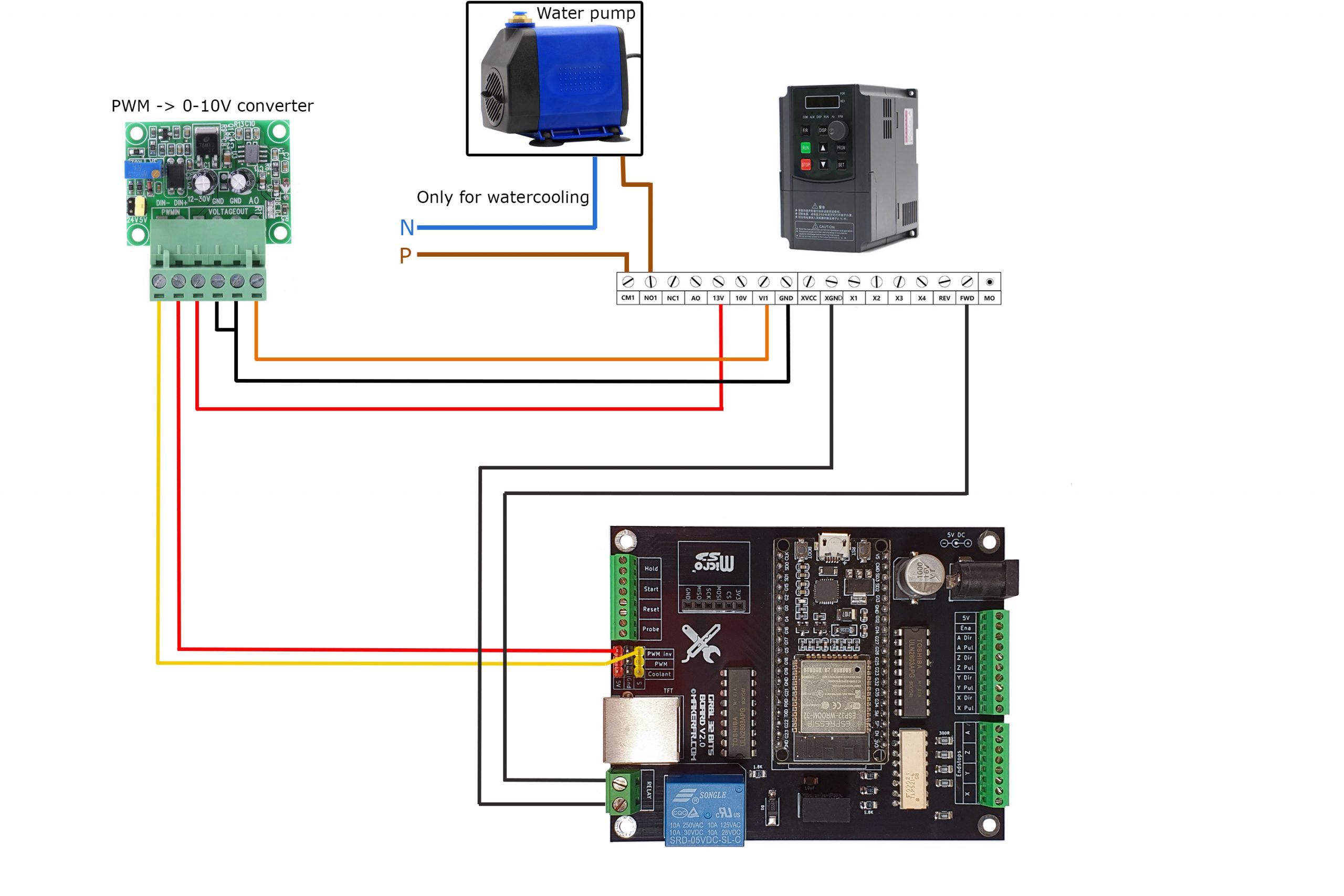
VFD wiring
This section talks about one of the most popular VFDs, type YL620 / YL620-A. If you have a different VFD, refer to your documentation to find the equivalent connection and settings.
Power wiring

Control wiring
VFD settings

To change the values explained below, proceed as follows:
- Press the PRGM button
- Go to the program number with the UP and DOWN buttons
- Press the SET button
- Modify the program value with the UP and DOWN buttons
- Validate the new value by pressing the SET button
- Activate an external command source: Program P00.01, value 1
- Maximum frequency at 400Hz (if your spindle turns at 400Hz max): Program P03.13, value 400
- Analogue external frequency source: Program P07.08, value 3
- Activate the VFD relay (if you have water cooling): Program P04.03, value 1
Important: At the first test of the vacuum spindle, check the correct direction of rotation of the spindle, if it does not rotate in the correct direction, reverse the W and V wires of the spindle on the VFD.
Laser Wiring
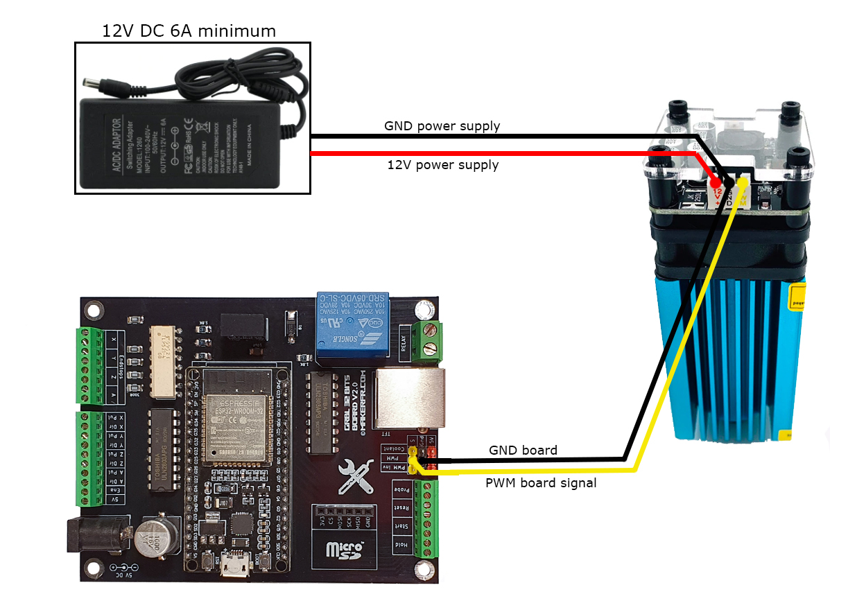
- On the V2.0 board, the laser mode is only activated via the command $Spindle/Type=Laser (otherwise the M4 S *** command will not work)
- To return to milling mode, send the command $Spindle/Type=PWM
- You can create personalized buttons on the TFT to activate the laser mode and the spindle mode (see TFT user manual page)